HP FlexFabric 7900 Switch Series Installation Guide Part number: 5998-4299 Document version: 5W100-20131203
Legal and notice information © Copyright 2013 Hewlett-Packard Development Company, L.P. No part of this documentation may be reproduced or transmitted in any form or by any means without prior written consent of Hewlett-Packard Development Company, L.P. The information contained herein is subject to change without notice.
Contents Preparing for installation ············································································································································· 1 Safety recommendations ·················································································································································· 1 Examining the installation site ································································································································
Determining the master switch and planning IRF member IDs ········································································· 29 Planning IRF topology and connections ·············································································································· 29 Determining physical IRF ports on the member switches ·················································································· 31 Planning the cabling scheme ·························································
Index ··········································································································································································· 53 iii
Preparing for installation Table 1 HP FlexFabric 7900 Switch Series models Product code HP description Alias JG682A HP FlexFabric 7904 Switch Chassis HP 7904 For regulatory identification purposes, the HP FlexFabric 7904 Switch Chassis is assigned a regulatory model number (RMN) BJNGA-AC0012. This regulatory number should not be confused with the marketing name HP FlexFabric 7904, or product code JG682A.
• Identify the airflow designs of neighboring devices, and prevent hot air flowing out of the bottom device from entering the top device. • The rack or workbench is sturdy enough to support the switch and its accessories. • The rack or workbench is correctly grounded. To ensure correct operation and long service life of the switch, install it in an environment that meets the requirements described in the following subsections.
• Capacitive coupling • Inductive coupling • Radiative coupling • Common impedance coupling • Conductive coupling To prevent EMI, take the following actions: • If AC power is used, use a single-phase three-wire power receptacle with protection earth (PE) to filter interference from the power grid. • Keep the switch far away from radio transmitting stations, radar stations, and high-frequency devices to make sure the EMI levels do not exceed the compliant range.
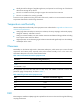
Installing the switch CAUTION: Keep the tamper-proof seal on a mounting screw on the chassis cover intact, and if you want to open the chassis, contact HP for permission. Otherwise, HP shall not be liable for any consequence. Figure 1 Hardware installation flow Installing the switch in a 19-inch rack Mounting bracket and cable management bracket kit The HP 7904 switch comes with a pair of mounting brackets and a cable management bracket attached together. You can detach them as required.
Figure 2 2U mounting bracket and cable management bracket kit (1) Cable management bracket (2) Mounting bracket Rack mounting rail kit The HP 7904 switch also comes with a pair of chassis rails and a pair of slide rails. Figure 3 Rack mounting rail kit (1) Chassis rail (2) Slide rail Rack-mounting procedures at a glance You can install the HP 7904 switch in a 19-inch rack using the mounting bracket and rack mounting rail kit as described in Figure 4.
NOTE: • To install the HP 7904 switch in a 19-inch rack, make sure the distance from the front post to the front door is no less than 100 mm (3.94 in), the distance from the front post to the rear post is in the range from 590 mm (23.23 in) to 980 mm (38.58 in), and the distance from the front post to the rear door is no less than 830 mm (32.68 in).
Connecting the grounding cable to the chassis CAUTION: The primary grounding point and auxiliary grounding point are located on the left side panel. If you use one of these grounding points, you must connect the grounding cable to the grounding point before you mount the switch in the rack. To connect the grounding cable to a chassis grounding point, for example, the primary grounding point: 1. Unpack the grounding cable and grounding screws. 2.
Figure 7 Attaching the mounting brackets, and chassis rails to the chassis (network port side mounting position) Rack-mounting the switch Attaching the slide rails to the rack 1. Determine the rack attachment position for the slide rails. 2. Install cage nuts (user-supplied) in the mounting holes in the rack posts. 3. Align the screw holes in one slide rail with the cage nuts in the rack post on one side, and use screws (user supplied) to attach the slide rail to the rack, as shown in Figure 8. 4.
Mounting the switch in the rack This task requires two people. To mount the switch in the rack: 1. Wear an ESD wrist strap and make sure it makes good skin contact and is correctly grounded. 2. Verify that the mounting brackets and chassis rails have been securely attached to the switch chassis. 3. Verify that the slide rails have been correctly attached to the rear rack posts. 4. Install cage nuts (user-supplied) to the front rack posts and make sure they are at the same level as the slide rails.
Figure 10 Mounting the switch in the rack (2) Grounding the switch WARNING! Correctly connecting the switch grounding cable is crucial to lightning protection and EMI protection. The power input end of the switch has a noise filter, whose central ground is directly connected to the chassis to form the chassis ground (commonly known as PGND).
2. Remove the hex nut of a grounding post on the grounding strip. 3. Attach the ring terminal at the other end of the grounding cable to the grounding strip through the grounding post, and fasten the ring terminal with the removed hex nut.
Figure 12 Grounding through the PE wire of the AC power cord NOTE: To guarantee the grounding effect, HP recommends that you use the grounding cable provided with the switch to connect to the grounding strip in the equipment room. Installing/removing a fan tray CAUTION: The HP 7904 switch has two fan tray slots. To ensure good ventilation, follow these guidelines: • Do not operate the switch without a fan tray. • You must install two fan trays of the same model on the switch.
5. Holding the fan tray with both hands with the upside (marked with a "TOP" sign) up, gently push the fan tray into the slot along the guide rails until the fan tray completely seats into the slot. See callout 3 in Figure 13. 6. Use a Phillips screwdriver to tighten the captive screws on the fan tray to make sure the fan tray is fully seated in the slot. Figure 13 Installing a fan tray 1 2 3 Removing a fan tray WARNING! • The new fan tray and the removed fan tray must be the same model.
3. Grasp the handle of the fan tray with one hand and pull the fan tray part way out the slot. Support the fan tray bottom with the other hand, and pull the fan tray slowly along the guide rails out of the slot. 4. Put the removed fan tray into the antistatic bag.
Figure 16 Installing a power supply If a blank panel is installed in the power supply slot, remove the blank panel before installing the power supply. Thread a flat-blade screwdriver through the power supply handle and pull out the blank panel gently as shown in Figure 17.
NOTE: To ensure good ventilation, install blank panels to the empty power supply slot. Removing a power supply 1. Wear an ESD wrist strap and make sure it makes good skin contact and is correctly grounded. 2. Release the cable tie securing the power cable to the handle and remove the power cord from the power supply. 3.
Figure 19 Connecting the AC power cord to the switch 2 1 (1) Cable tie (2) Secure the power cord to the power supply handle using the cable tie Installing/removing an LPU CAUTION: Do not touch the surface-mounted components directly with your hands when installing or removing an LPU. The HP 7904 switch comes with blank panels installed in all LPU slots except slot 1. For LPUs available for the HP FlexFabric 7900 Switch Series, see "Appendix B FRUs and compatibility matrixes.
Figure 20 Installing an LPU (1) LPU-pushing direction (2) Ejector lever-pushing direction (3) Screw-tightening direction Removing an LPU 1. Wear an ESD wrist strap and make sure it makes good skin contact and is correctly grounded. 2. Use a Phillips screwdriver to completely loosen the captive screws at both sides of the LPU. 3. Pull the ejector levers at both sides of the LPU outward, and pull the LPU along the guide rails until it completely comes out of the switch chassis.
• The grounding cable is securely connected. • The correct power source is used. • The power cords are correctly connected.
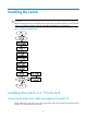
Accessing the switch for the first time Setting up the configuration environment The first time you access the switch you must use a console cable to connect a console terminal, for example, a PC, to the console port on the switch, as shown in Figure 22.
To connect a terminal, for example, a PC, to the switch: 1. Plug the DB-9 female connector of the console cable to the serial port of the PC. 2. Connect the RJ-45 connector to the console port of the switch. NOTE: Identify the mark on the console port and make sure you are connecting to the correct port. Setting terminal parameters To configure and manage the switch, you must run a terminal emulator program on the console terminal.
Figure 25 Setting the serial port used by the HyperTerminal connection 4. Set Bits per second to 9600, Data bits to 8, Parity to None, Stop bits to 1, and Flow control to None, and click OK.
5. Select File > Properties in the HyperTerminal window. Figure 27 HyperTerminal window 6. On the Settings tab, set the emulation to VT100 and click OK.
Powering on the switch Before powering on the switch, confirm the following: • The switch has been securely mounted. • All the cards have been correctly installed. • The unused slots have been installed with blank panels. • All the network cables, fibers, power cables, and grounding cables have been correctly connected. • The input power voltage meets the requirement of the switch.
Authentication method Feature Application scenarios Username and password Complex to configure, secure, and hierarchical user management Environments where multiple user roles cooperate to manage the switch For more information about login methods, see HP FlexFabric 7900 Switch Series Fundamentals Configuration Guide. Configuring the basic access function The switch can perform basic data forwarding immediately after it is plugged into a network.
Configure static routes • # Configure a static route, with the destination IP address 172.16.1.0 and the next hop IP address 192.168.0.2. [Sysname] ip route-static 172.16.1.0 255.255.255.0 192.168.0.2 Configure VLANs • # Create VLAN 10 and enter its view. [Sysname] vlan 10 [Sysname-vlan10] # Assign port Ten-GigabitEthernet 1/0/1 to VLAN 10.
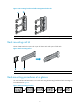
{ For information about how to connect an MPO connector, see Figure 30. Figure 29 Using an LC optical fiber connector to connect an SFP module Figure 30 Using an MPO optical fiber connector to connect a QSFP module 4. Verify the connection by examining the port LEDs. For more information about the LEDs, see "Appendix C Ports and LEDs." Testing connectivity After you plug the switch into the network, use the ping or tracert command to test the network connectivity.
Setting up an IRF fabric You can use HP Intelligent Resilient Framework (IRF) technology to connect and virtualize multiple switches into a large virtual switch called an "IRF fabric" for flattened network topology, and high availability, scalability, and manageability. IRF fabric setup flowchart Figure 31 IRF fabric setup flowchart To set up an IRF fabric: Step Description 1. • • • • • Plan IRF fabric setup.
Step Description 2. Install IRF member switches. See "Preparing for installation" and "Installing the switch." 3. Power on the switches. N/A 4. Configure basic IRF settings on each switch in standalone mode. See HP FlexFabric 7900 Switch Series IRF Configuration Guide. 5. Connect the physical IRF ports. Connect physical IRF ports on switches. 6. Enable IRF mode. See HP FlexFabric 7900 Switch Series IRF Configuration Guide. 7. Verify the IRF settings.
When connecting two neighboring IRF member switches, you must connect the physical ports of IRF-port 1 on one switch to the physical ports of IRF-port 2 on the other switch. You can create an IRF fabric in daisy chain topology or more reliable ring topology. In ring topology, the failure of one IRF link does not cause the IRF fabric to split as in daisy chain topology. Instead, the IRF fabric changes to a daisy chain topology without interrupting network services.
Figure 33 IRF fabric in ring topology 1 2 3 IRF-port1 IRF-port2 1 IRF-port1 IRF-port2 IRF-port1 IRF-port2 2 3 Determining physical IRF ports on the member switches Determine the physical IRF ports on the member switches according to your topology and connection scheme. You can use 40-GE ports on the switch for IRF connection. The switch supports multi-card link aggregation for IRF ports. You can bind up to eight physical ports to one IRF port.
Figure 34 Connecting the switches in one rack Figure 35 IRF fabric topology Connecting the IRF member switches in a ToR solution You can install IRF member switches in different racks side by side to deploy a top of rack (ToR) solution. Figure 36 shows an example for connecting 4 top of rack IRF member switches by using QSFP+ transceiver modules and optical fibers. The topology is the same as Figure 35.
Configure basic IRF settings as planned. For more information about configuring basic IRF settings, see HP FlexFabric 7900 Switch Series IRF Configuration Guide. Connecting the physical IRF ports Use QSFP+ cables or QSFP+ transceiver modules and fibers to connect the IRF member switches as planned. Wear an ESD wrist strap when you connect QSFP+ cables or QSFP+ transceiver modules and fibers. For how to connect them, see QSFP+ Transceiver Modules Installation Guide.
Maintenance and troubleshooting To avoid switch failures, maintain the switch as follows: • Clean your switch periodically. • Make sure the switch operates in a compliant environment. • Verify the installation environments against the requirements in "Preparing for installation." • Periodically perform the power-on test for the spare switches. When the switch fails, you can locate the failures by using related display commands or by LEDs.
• Parity—none • Stop bits—1 • Flow control—none Power supply failure When a power supply is operating correctly, its input and output LEDs are steady green. When its input or output LED is red, the power supply is faulty. To troubleshoot the power supply: 1. Verify that the power supply model is as required. For more information about power supplies available for the switch, see "Appendix B FRUs and compatibility matrixes." 2. Check for loose power cord connection, and reconnect the power cord.
2. Calculate the total power consumption, and make sure the power supplies can provide enough power. For more information, see "Appendix A Chassis views and technical specifications." 3. Verify that the LPU is fully seated by removing and reinstalling the LPU. For more information about installing an LPU, see "Installing/removing an LPU." 4. If the switch has empty card slots, install the card into another slot. If the card can operate correctly, the previous slot is faulty. 5.
Support and other resources Contacting HP For worldwide technical support information, see the HP support website: http://www.hp.
Conventions This section describes the conventions used in this documentation set. Command conventions Convention Description Boldface Bold text represents commands and keywords that you enter literally as shown. Italic Italic text represents arguments that you replace with actual values. [] Square brackets enclose syntax choices (keywords or arguments) that are optional. { x | y | ... } Braces enclose a set of required syntax choices separated by vertical bars, from which you select one.
Network topology icons Represents a generic network device, such as a router, switch, or firewall. Represents a routing-capable device, such as a router or Layer 3 switch. Represents a generic switch, such as a Layer 2 or Layer 3 switch, or a router that supports Layer 2 forwarding and other Layer 2 features. Represents an access controller, a unified wired-WLAN module, or the switching engine on a unified wired-WLAN switch. Represents an access point.
Appendix A Chassis views and technical specifications The HP FlexFabric 7900 Switch Series includes only one model: HP FlexFabric 7904 Switch Chassis. An HP 7904 switch has an MPU section, an LPU section, a power supply section, and a fan tray section. The MPU is built into the switch. The LPUs, fan trays, and power supplies are field replaceable unit (FRUs). Unless otherwise stated, an LPU is referred to as a "card" in this document.
Figure 38 Rear view of the HP 7904 switch (1) Power supply slots (2) From top down: console port and management Ethernet port (3) From top down: system status LED (SYS), ID LED, fan status LED (FAN), reset button (RST), and LPU status LED (SLOT) (4) Fan tray slots (5) USB port NOTE: • There are two power supply slots on the rear panel of the HP 7904 chassis. The switch comes with the power supply slots empty. Filler panels are included in the accessory kit. You can install one or two power supplies.
Table 7 Weight Item Model Net weight Chassis HP 7904 15.5 kg (34.17 lb) LPU LSV1QGS12SA1 2.5 kg (5.51 lb) Fan tray • Back-to-front airflow fan tray (JG839A) • Front-to-back airflow fan tray (JG684A) 0.9 kg (1.98 lb) Power supply PSR1800-56A 1.6 kg (3.53 lb) Chassis dimensions and rack clearance requirements Table 8 lists dimensions for the switch chassis installed with no FRUs, transceiver modules, or accessories. Table 8 Chassis dimensions Model Height Weight Depth HP 7904 88.1 mm (3.
Module power consumption and system power consumption Card power consumption The power consumption of the card depends on the card state. Table 10 lists the power consumption for the LSV1QGS12SA1. • Static power consumption—Power consumed by the card when the card is running but all ports on the card are down and no transceiver modules are installed on the fiber ports of the card. • Dynamic power consumption—Power consumed by the card when the card is fully configured and sends broadcasts at wire speed.
Environmental specifications Table 12 Environmental specifications Item Operating environment Non-operating environment Temperature 0°C to 40°C (32°F to 104°F) –40°C to +70°C (–40°F to +158°F) 5% to 95% 5% to 95% Relative humidity (noncondensing) Noise The switch uses fans with the automatic speed adjustment function, so the sound pressure levels vary by fan speed. For more information, see Table 13.
• When a front-to-back airflow fan tray (JG684A) is used, ambient air flows in through the air vents in the port-side panel, circulates through the chassis and the power supplies, and exhausts through the air vents in the fan tray panel and the power supply panels, as shown in Figure 41.
Appendix B FRUs and compatibility matrixes LPUs The LPU listed in Table 15 applies to the HP FlexFabric 7900 switch series. For more information about the transceiver modules supported by the LPU, see "Transceiver modules.
NOTE: You can install one power supply if the input voltage is in the range of 200 VAC to 240 VAC. You must install two power supplies if the input voltage is in the range of 100 VAC to 200 VAC. Fan trays Order the fan trays compatible with your switch if necessary. To ensure correct operation of the switch, make sure you install two fan trays of the same model on the switch. Table 17 describes the specifications of fan trays used by the HP 7904 switch.
Table 19 QSFP+ cable specifications Product code Description Cable length JG326A HP X240 40G QSFP+ QSFP+ 1m Direct Attach Copper Cable 1 m (3.28 ft) JG327A HP X240 40G QSFP+ QSFP+ 3m Direct Attach Copper Cable 3 m (9.84 ft) JG328A HP X240 40G QSFP+ QSFP+ 5m Direct Attach Copper Cable 5 m (16.40 ft) Remarks Used for connecting 40 Gbps QSFP+ ports.
Appendix C Ports and LEDs Ports Console port The HP 7904 switch has one console port. Table 21 Console port specifications Item Description Connector type RJ-45 Compliant standard EIA/TIA-232 Transmission baud rate 9600 bps (default) to 115200 bps Services • Provides connection to an ASCII terminal. • Provides connection to the serial port of a local or remote (through a pair of modems) PC running terminal emulation program.
LEDs System status LED The system status LED shows the operating status of the switch. Table 23 System status LED description LED SYS Status Description Steady green The switch is booting up. Flashing green The switch is operating correctly. Flashing red Faults have occurred on the switch. Off The switch is powered off. ID LED Each switch has an ID LED to show the IRF member switch role.
Table 26 LPU status LED description LED SLOT Status Description Steady green The LPU is starting. Flashing green The LPU is operating correctly. Flashing red The LPU is faulty. Off The LPU is powered off. Management Ethernet port LEDs A management Ethernet port has one LINK LED and one ACT LED to show its link and data transmission status.
Table 29 Power supply LED description LED AC OK DC OK Status Description Steady green Power input is normal. Off No power is being input or the power supply has an input problem. Steady green Power output is normal. Steady red The power supply has an output problem. Off No power is being output.
Index CEFGHILOPRSTV C IRF fabric setup flowchart,28 Chassis views,40 L Configuration terminal problems,34 LEDs,50 Configuring basic IRF settings,32 LPU failure,35 Configuring the switch,24 LPUs,46 Connecting the console cable,20 O Connecting the physical IRF ports,33 Other specifications,44 Connecting the power cord,16 Connecting the switch to the network,26 P Contacting HP,37 Planning IRF fabric setup,29 Conventions,38 Ports,49 Cooling system,44 Power supplies,46 E Power supply failu