HP FlexFabric 7900 Switch Series ACL and QoS Configuration Guide Part number: 5998-4285 Software version: Release 2109 Document version: 6W100-20140122
Legal and notice information © Copyright 2014 Hewlett-Packard Development Company, L.P. No part of this documentation may be reproduced or transmitted in any form or by any means without prior written consent of Hewlett-Packard Development Company, L.P. The information contained herein is subject to change without notice.
Contents Configuring ACLs ························································································································································· 1 Overview············································································································································································ 1 Applications on the switch ························································································································
Configuring a priority map ··········································································································································· 23 Configuring a port to trust packet priority for priority mapping ··············································································· 23 Changing the port priority of an interface ·················································································································· 24 Displaying and maintaining priori
Configuring traffic redirecting ··································································································································· 55 Configuration procedure ··············································································································································· 55 Configuration example ·················································································································································· 56 Ne
Configuring ACLs Overview An access control list (ACL) is a set of rules (or permit or deny statements) for identifying traffic based on criteria such as source IP address, destination IP address, and port number. ACLs are primarily used for packet filtering. "Configuring packet filtering with ACLs" provides an example. You can use ACLs in QoS, security, routing, and other feature modules for identifying traffic. The packet drop or forwarding decisions varies with the modules that use ACLs.
Match order The rules in an ACL are sorted in a specific order. When a packet matches a rule, the device stops the match process and performs the action defined in the rule. If an ACL contains overlapping or conflicting rules, the matching result and action to take depend on the rule order. The following ACL match orders are available: • config—Sorts ACL rules in ascending order of rule ID. A rule with a lower ID is matched before a rule with a higher ID.
By introducing a gap between rules rather than contiguously numbering rules, you have the flexibility of inserting rules in an ACL. This feature is important for a config-order ACL, where ACL rules are matched in ascending order of rule ID. Automatic rule numbering and renumbering The ID automatically assigned to an ACL rule takes the nearest higher multiple of the numbering step to the current highest rule ID, starting with 0.
Step Command 5. Create or edit a rule. rule [ rule-id ] { deny | permit } [ counting | fragment | source { source-address source-wildcard | any } | time-range time-range-name ] * 6. (Optional.) Add or edit a rule comment. rule rule-id comment text Remarks By default, an IPv4 basic ACL does not contain any rule. If an IPv4 basic ACL is for outbound QoS traffic classification or packet filtering, it does not support the counting keyword, and it takes effect on only Layer 3 packets.
Step 5. 6. Command Create or edit a rule. (Optional.) Add or edit a rule comment.
Step Command Remarks By default, an Ethernet frame header ACL does not contain any rule. Create or edit a rule. 5.
NOTE: The ACL-based packet filter function is available on Layer 2 and Layer 3 Ethernet interfaces, and VLAN interfaces. The term "interface" in this section collectively refers to these types of interfaces. You can use the port link-mode command to configure an Ethernet port as a Layer 2 or Layer 3 interface (see Layer 2—LAN Switching Configuration Guide). Applying an ACL to an interface for packet filtering Step Command Remarks 1. Enter system view. system-view N/A 2. Enter interface view.
Task Command Display match statistics for packet filtering ACLs. display packet-filter statistics interface interface-type interface-number { inbound | outbound } [ acl-number | name acl-name ] [ brief ] Display the accumulated statistics for packet filtering ACLs. display packet-filter statistics sum { inbound | outbound } { acl-number | name acl-name } [ brief ] Display detailed ACL packet filtering information (in standalone mode).
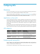
Figure 1 Network diagram Configuration procedure # Create a periodic time range from 8:00 to 18:00 on working days. system-view [DeviceA] time-range work 08:0 to 18:00 working-day # Create an IPv4 advanced ACL numbered 3000 and configure three rules in the ACL.
Reply from 192.168.0.100: bytes=32 time<1ms TTL=255 Reply from 192.168.0.100: bytes=32 time<1ms TTL=255 Reply from 192.168.0.100: bytes=32 time<1ms TTL=255 Ping statistics for 192.168.0.100: Packets: Sent = 4, Received = 4, Lost = 0 (0% loss), Approximate round trip times in milli-seconds: Minimum = 0ms, Maximum = 1ms, Average = 0ms The output shows that the database server can be pinged. # Ping the database server from a PC in the Marketing department during the working hours. C:\> ping 192.168.0.
QoS overview In data communications, Quality of Service (QoS) provides differentiated service guarantees for diversified traffic in terms of bandwidth, delay, jitter, and drop rate, all of which can affect QoS. Network resources are limited. When configuring a QoS scheme, you must consider the characteristics of different applications. For example, when bandwidth is fixed, more bandwidth used by one user leaves less bandwidth for others.
QoS techniques overview The QoS techniques include traffic classification, traffic policing, traffic shaping, rate limit, congestion management, and congestion avoidance. The following section briefly introduces these QoS techniques. All QoS techniques in this document are based on the DiffServ model.
Configuring a QoS policy You can configure QoS by using the MQC approach or non-MQC approach. Some features support both approaches, but some support only one. Non-MQC approach In the non-MQC approach, you configure QoS service parameters without using a QoS policy. For example, you can use the rate limit feature to set a rate limit on an interface without using a QoS policy. MQC approach In the modular QoS configuration (MQC) approach, you configure QoS service parameters by using QoS policies.
Defining a traffic class Configuration guidelines If a class that uses the AND operator has multiple if-match acl or if-match service-vlan-id clauses, a packet that matches any of the clauses matches the class.
Option Description Matches DSCP values. dscp dscp-value&<1-8> The dscp-value&<1-8> argument is a list of DSCP values. A DSCP value ranges from 0 to 63 or can be a keyword shown Table 3. &<1-8> indicates that you can enter up to eight DSCP values. Matches IP precedence. ip-precedence ip-precedence-value&<1-8> protocol protocol-name The ip-precedence-value&<1-8> argument is a list of IP precedence values. An IP precedence ranges from 0 to 7.
Keyword DSCP value (binary) DSCP value (decimal) cs4 100000 32 cs5 101000 40 cs6 110000 48 cs7 111000 56 ef 101110 46 Defining a traffic behavior A traffic behavior is a set of QoS actions (such as traffic filtering, shaping, policing, and priority marking) to take on a traffic class of traffic. To define a traffic behavior: Step Command Remarks 1. Enter system view. system-view N/A 2. Create a traffic behavior and enter traffic behavior view.
Applying the QoS policy You can apply a QoS policy to the following destinations: • An interface—The QoS policy takes effect on the traffic sent or received on the interface. • A VLAN—The QoS policy takes effect on the traffic sent or received on all ports in the VLAN. • Globally—The QoS policy takes effect on the traffic sent or received on all ports. You can modify traffic classes, traffic behaviors, and class-behavior associations in a QoS policy even after it is applied.
Step Command Remarks 1. Enter system view. system-view N/A 2. Apply the QoS policy to VLANs. qos vlan-policy policy-name vlan vlan-id-list { inbound | outbound } By default, no QoS policy is applied to a VLAN. Applying the QoS policy globally You can apply a QoS policy globally to the inbound or outbound direction of all ports. To apply the QoS policy globally: Step Command Remarks 1. Enter system view. system-view N/A 2. Apply the QoS policy globally.
Display information about QoS policies applied globally (in standalone mode). display qos policy global [ slot slot-number ] [ inbound | outbound ] Display information about QoS policies applied globally (in IRF mode). display qos policy global [ chassis chassis-number slot slot-number ] [ inbound | outbound ] Clear the statistics of the QoS policy applied in a certain direction of a VLAN.
Configuring priority mapping Overview When a packet arrives, depending on your configuration, a device assigns a set of QoS priority parameters to the packet based on either a certain priority field carried in the packet or the port priority of the incoming port. This process is called "priority mapping." During this process, the device can modify the priority of the packet according to the priority mapping rules.
Priority trust mode on a port The priority trust mode on a port determines which priority is used for priority mapping table lookup. Port priority was introduced to use for priority mapping in addition to the priority fields carried in packets. The Switch Series provides the following priority trust modes: Using the 802.1p priority carried in packets for priority mapping. • Table 4 Priority mapping results of trusting the 802.1p priority (when the default dot1p-lp priority mapping table is used) 802.
Priority mapping process On receiving an Ethernet packet on a port, the switch marks the scheduling priorities (local precedence and drop precedence) for the Ethernet packet. This process is done according to the priority trust mode of the receiving port and the 802.1q tagging status of the packet, as shown in Figure 4.
Tasks at a glance (Optional.) Configuring a priority map (Required.) Perform one of the following tasks: • Configuring a port to trust packet priority for priority mapping • Changing the port priority of an interface Configuring a priority map The term "interface" in this section collectively refers to Layer 2 and Layer 3 Ethernet interfaces. You can use the port link-mode command to configure an Ethernet port as a Layer 2 or Layer 3 interface (see Layer 2—LAN Switching Configuration Guide).
• Configure the interface to trust 3. Configure the trusted packet priority type. the DSCP precedence. qos trust dscp • Configure the interface to trust the 802.1p priority of received packets. undo qos trust Use one of these commands. By default, the interface trusts the 802.1p priority. Changing the port priority of an interface If an interface does not trust any packet priority, the device uses its port priority to look for the set of priority parameters for the incoming packets.
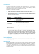
Figure 5 Network diagram Device A Internet FG E1 /0/ 1 2 /0/ E1 G F Server FGE1/0/3 Device C Device B Configuration procedure # Assign port priority to FortyGigE 1/0/1 and FortyGigE 1/0/2. Make sure that the priority of FortyGigE 1/0/1 is higher than that of FortyGigE 1/0/2, and that no trusted packet priority type is configured on FortyGigE 1/0/1 or FortyGigE 1/0/2.
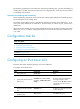
Traffic destination Traffic priority order management department > marketing department Internet Management department > marketing department > R&D department Queuing plan Traffic source Output queue Queue priority Management department 4 Medium Marketing department 2 Low R&D department 2 Low Management department 6 High Marketing department 4 Medium Figure 6 Network diagram Internet Host Host Server Server FGE1/0/5 Mgmt Dept FGE1/0/3 FGE1/0/2 FGE1/0/1 FGE1/0/4 Data server R&D
[Device] interface FortyGigE 1/0/3 [Device-FortyGigE1/0/3] qos priority 5 [Device-FortyGigE1/0/3] quit 2. Configure the 802.1p-to-local mapping table to map 802.1p priority values 3, 4, and 5 to local precedence values 2, 6, and 4. This guarantees the R&D department, management department, and marketing department decreased priorities to access the public server.
[Device-qospolicy-rd] quit [Device] interface FortyGigE 1/0/2 [Device-FortyGigE1/0/2] qos apply policy rd inbound 28
Configuring traffic policing, GTS, and rate limit Overview Traffic policing helps assign network resources (including bandwidth) and increase network performance. For example, you can configure a flow to use only the resources committed to it in a certain time range. This avoids network congestion caused by burst traffic. Traffic policing, Generic Traffic Shaping (GTS), and rate limit control the traffic rate and resource usage according to traffic specifications.
CBS is implemented with bucket C, and EBS with bucket E. When only the CIR is used for traffic evaluation, packets are measured against the following bucket scenarios: • If bucket C has enough tokens, packets are colored green. • If bucket C does not have enough tokens but bucket E has enough tokens, packets are colored yellow. • If neither bucket C nor bucket E has sufficient tokens, packets are colored red.
GTS GTS supports shaping the outbound traffic. GTS limits the outbound traffic rate by buffering exceeding traffic. You can use GTS to adapt the traffic output rate on a device to the input traffic rate of its connected device to avoid packet loss. The differences between traffic policing and GTS are as follows: • Packets to be dropped with traffic policing are retained in a buffer or queue with GTS, as shown in Figure 8.
Rate limit also uses token buckets for traffic control. When rate limit is configured on an interface, a token bucket handles all packets to be sent through the interface for rate limiting. If enough tokens are in the token bucket, packets can be forwarded. Otherwise, packets are put into QoS queues for congestion management. In this way, the traffic passing the physical interface is controlled. Figure 10 Rate limit implementation The token bucket mechanism limits traffic rate when accommodating bursts.
Step Command Remarks 7. Return to system view. quit N/A 8. Create a QoS policy and enter QoS policy view. qos policy policy-name By default, no QoS policy is configured. Associate the traffic class with the traffic behavior in the QoS policy. classifier classifier-name behavior behavior-name By default, a traffic class is not associated with a traffic behavior. quit N/A • Applying the QoS policy to an Choose one of the application destinations as needed. 9. 10. Return to system view. 11.
Step Command Remarks 1. Enter system view. system-view N/A 2. Enter interface view. interface interface-type interface-number N/A 3. Configure the rate limit for the interface. qos lr outbound cir committed-information-rate [ cbs committed-burst-size ] By default, rate limit is not configured on an interface. Displaying and maintaining traffic policing, GTS, and rate limit Execute display commands in any view. Task Command Display QoS and ACL resource usage (in standalone mode).
Figure 11 Network diagram Server Internet Host A Device B FGE1/0/2 1.1.1.1/8 Ethernet 1.1.1.2/8 FGE1/0/1 Host B FGE1/0/1 Device A FGE1/0/3 FGE1/0/2 Configuration procedures 1. Configure Device A: # Configure ACL 2001 and ACL 2002 to match traffic from Server and Host A, respectively. system-view [DeviceA] acl number 2001 [DeviceA-acl-basic-2001] rule permit source 1.1.1.1 0 [DeviceA-acl-basic-2001] quit [DeviceA] acl number 2002 [DeviceA-acl-basic-2002] rule permit source 1.1.1.
# Apply QoS policy car to the incoming traffic of port FortyGigE 1/0/1. [DeviceA] interface FortyGigE 1/0/1 [DeviceA-FortyGigE1/0/1] qos apply policy car inbound 2. Configure Device B: # Configure advanced ACL 3001 to match HTTP traffic. system-view [DeviceB] acl number 3001 [DeviceB-acl-adv-3001] rule permit tcp destination-port eq 80 [DeviceB-acl-adv-3001] quit # Create a class named http and use ACL 3001 as the match criterion.
Configuring congestion management Overview Congestion occurs on a link or node when traffic size exceeds the processing capability of the link or node. It is typical of a statistical multiplexing network and can be caused by link failures, insufficient resources, and various other causes. Figure 12 shows two typical congestion scenarios.
Figure 13 SP queuing In Figure 13, SP queuing classifies eight queues on a port into eight classes, numbered 7 to 0 in descending priority order. SP queuing schedules the eight queues in the descending order of priority. SP queuing sends packets in the queue with the highest priority first. When the queue with the highest priority is empty, it sends packets in the queue with the second highest priority, and so on.
Figure 14 WRR queuing Queue 0 Weight 1 Packets to be sent through this port Queue 1 Weight 2 Sent packets Interface …… Queue N-2 Weight N-1 Queue scheduling Packet classification Sending queue Queue N-1 Weight N Assume a port provides eight output queues. WRR assigns each queue a weight value (represented by w7, w6, w5, w4, w3, w2, w1, or w0) to decide the proportion of resources assigned to the queue.
SP+WRR queuing You can implement SP+WRR queuing by configuring some queues on an interface to use SP queuing and others to use WRR queuing. With this SP+WRR queuing method, the system schedules queues in the following order: 1. Schedules the queues in the SP group. 2. Schedules queues in the WRR group when all queues in the SP group are empty. The queues in the SP group are scheduled based on their priorities. The queues in the WRR group are scheduled based on their weights.
Configuring SP queuing Configuration procedure To configure SP queuing: Step Command Remarks 1. Enter system view. system-view N/A 2. Enter interface view. interface interface-type interface-number N/A 3. (Optional.) Configure SP queuing. qos sp The default queuing algorithm on an interface is SP queuing. Configuration example Configure FortyGigE 1/0/1 to use SP queuing: # Enter system view system-view # Configure FortyGigE 1/0/1 to use SP queuing.
# Enter system view. system-view # Configure WRR queuing on FortyGigE 1/0/1.
[Sysname] interface FortyGigE 1/0/1 [Sysname-FortyGigE1/0/1] qos wfq byte-count [Sysname-FortyGigE1/0/1] qos wfq 1 group 1 byte-count 2 [Sysname-FortyGigE1/0/1] qos wfq 3 group 1 byte-count 5 [Sysname-FortyGigE1/0/1] qos wfq 4 group 1 byte-count 10 [Sysname-FortyGigE1/0/1] qos wfq 5 group 1 byte-count 10 [Sysname-FortyGigE1/0/1] qos wfq 6 group 1 byte-count 10 [Sysname-FortyGigE1/0/1] qos wfq 0 group 1 byte-count 1 [Sysname-FortyGigE1/0/1] qos wfq 2 group 1 byte-count 2 [Sysname-FortyGigE1/0/1] qos wfq 7 gr
2. Configuration procedure # Enter system view. system-view # Configure SP+WRR queuing on FortyGigE1/0/1.
2. Configuration procedure # Enter system view. system-view # Configure SP+WFQ queuing on FortyGigE 1/0/1.
Figure 16 Queue scheduling profile configured with both SP and WRR Q7 Q6 Q5 Q4 Q3 SP group Q2 Q1 Q0 WRR group 1 • Queue 7 has the highest priority. Its packets are sent preferentially. • Queue 6 has the second highest priority. Packets in queue 6 are sent when queue 7 is empty. • Queue 3, queue 4, and queue 5 are scheduled according to their weights. When both queue 6 and queue 7 are empty, WRR group 1 is scheduled.
Step Command • Configure a queue to use WRR: You can configure the same queue scheduling algorithm, SP+WRR, or SP+WFQ for all queues. However, you cannot configure WRR+WFQ for queues. • Configure a queue to use WFQ: In a queue scheduling profile, you can configure different queue scheduling algorithms for different queues. • Configure a queue to use SP: queue queue-id sp Configure queue scheduling parameters. 3. Remarks queue queue-id wrr group group-id { byte-count | weight } schedule-value a.
• Queue 0 has the lowest priority. Queue 0 is scheduled when all the other queues are empty. Configuration procedure # Enter system view. system-view # Create queue scheduling profile qm1. [Sysname] qos qmprofile qm1 [Sysname-qmprofile-qm1] # Configure queue 7 to use SP queuing. [Sysname-qmprofile-qm1] queue 7 sp # Assign queues 1, 2, 3, 4, 5, and 6 to the WRR group, with the weight of 1, 10, 20, 1, 5, and 10, respectively.
Configuring traffic filtering You can filter in or filter out traffic of a class by associating the class with a traffic filtering action. For example, you can filter packets sourced from a specific IP address according to network status. Configuration procedure To configure traffic filtering: Step Command Remarks 1. Enter system view. system-view N/A 2. Create a traffic class and enter traffic class view.
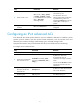
Configuration example Network requirements As shown in Figure 17, configure traffic filtering to filter the packets with source port not being 21, and received on FortyGigE 1/0/1. Figure 17 Network diagram Configuration procedure # Create advanced ACL 3000, and configure a rule to match packets whose source port number is 21.
Configuring priority marking Overview Priority marking sets the priority fields or flag bits of packets to modify the priority of packets. For example, you can use priority marking to set a DSCP value for a traffic class of IP packets to control the forwarding of these packets. To configure priority marking, you can associate a traffic class with a traffic behavior configured with the priority marking action to set the priority fields or flag bits of the traffic class of packets.
Step Command Remarks 8. Create a QoS policy and enter QoS policy view. qos policy policy-name By default, no QoS policy is configured. 9. Associate the traffic class with the traffic behavior in the QoS policy. classifier classifier-name behavior behavior-name By default, a traffic class is not associated with a traffic behavior. 10. Return to system view. quit N/A 11. Apply the QoS policy.
Figure 18 Network diagram Configuration procedure # Create advanced ACL 3000, and configure a rule to match packets with destination IP address 192.168.0.1. system-view [Device] acl number 3000 [Device-acl-adv-3000] rule permit ip destination 192.168.0.1 0 [Device-acl-adv-3000] quit # Create advanced ACL 3001, and configure a rule to match packets with destination IP address 192.168.0.2. [Device] acl number 3001 [Device-acl-adv-3001] rule permit ip destination 192.168.0.
[Device-classifier-classifier_fserver] quit # Create a traffic behavior named behavior_dbserver, and configure the action of setting the local precedence value to 4. [Device] traffic behavior behavior_dbserver [Device-behavior-behavior_dbserver] remark local-precedence 4 [Device-behavior-behavior_dbserver] quit # Create a traffic behavior named behavior_mserver, and configure the action of setting the local precedence value to 3.
Configuring traffic redirecting Traffic redirecting is the action of redirecting the packets matching the specific match criteria to a certain location for processing. The following redirect actions are supported: • Redirecting traffic to the CPU—Redirects packets that require processing by the CPU to the CPU. • Redirecting traffic to an interface—Redirects packets that require processing by an interface to the interface.
Step Command Remarks 8. Create a QoS policy and enter QoS policy view. qos policy policy-name By default, no QoS policy exists. 9. Associate the traffic class with the traffic behavior in the QoS policy. classifier classifier-name behavior behavior-name By default, no class-behavior association is configured for a QoS policy. 10. Return to system view. quit N/A 11. Apply the QoS policy.
Figure 19 Network diagram Configuration procedure # Create basic ACL 2000, and configure a rule to match packets with source IP address 2.1.1.1. system-view [DeviceA] acl number 2000 [DeviceA-acl-basic-2000] rule permit source 2.1.1.1 0 [DeviceA-acl-basic-2000] quit # Create basic ACL 2001, and configure a rule to match packets with source IP address 2.1.1.2. [DeviceA] acl number 2001 [DeviceA-acl-basic-2001] rule permit source 2.1.1.
[DeviceA] interface FortyGigE 1/0/1 [DeviceA-FortyGigE1/0/1] qos apply policy policy inbound 58
Configuring aggregate CAR An aggregate CAR action is created globally and can be directly applied to interfaces or referenced in the traffic behaviors associated with different traffic classes to police multiple traffic flows as a whole. The total rate of the traffic flows must conform to the traffic policing specifications set in the aggregate CAR action. Configuration procedure To configure aggregate CAR: Step Command Remarks 1. Enter system view. system-view N/A 2.
Figure 20 Network diagram Configuration procedure # Configure an aggregate CAR according to the rate limit requirements. system-view [Device] qos car aggcar-1 aggregative cir 2560 cbs 20000 red discard # Create class 1 to match traffic of VLAN 10. Create behavior 1 and reference the aggregate CAR in the behavior.
# Apply the QoS policy to the incoming traffic of FortyGigE 1/0/1.
Configuring class-based accounting Class-based accounting collects statistics (in packets or bytes) on a per-traffic class basis. For example, you can define the action to collect statistics for traffic sourced from a certain IP address. By analyzing the statistics, you can determine whether anomalies have occurred and what action to take. Configuration procedure To configure class-based accounting: Step Command Remarks 1. Enter system view. system-view N/A 2.
Step Command Remarks • In standalone mode: { { { 12. Display traffic accounting configuration. display qos policy global [ slot slot-number ] [ inbound | outbound ] display qos policy interface [ interface-type interface-number ] [ inbound | outbound ] display qos vlan-policy { name policy-name | vlan [ vlan-id ] } [ slot slot-number ] [ inbound | outbound ] • In IRF mode: { { { Available in any view.
[Device-classifier-classifier_1] if-match acl 2000 [Device-classifier-classifier_1] quit # Create a traffic behavior named behavior_1, and configure the class-based accounting action. [Device] traffic behavior behavior_1 [Device-behavior-behavior_1] accounting [Device-behavior-behavior_1] quit # Create a QoS policy named policy, and associate traffic class classifier_1 with traffic behavior behavior_1 in the QoS policy.
Configuring time ranges You can implement a service based on the time of the day by applying a time range to it. A time-based service only takes effect in any time periods specified by the time range. For example, you can implement time-based ACL rules by applying a time range to them. If a time range does not exist, the service based on the time range does not take effect. The following basic types of time range are available: • Periodic time range—Recurs periodically on a day or days of the week.
Figure 22 Network diagram Configuration procedure # Create a periodic time range during 8:00 and 18:00 on working days from June 2013 to the end of the year. system-view [DeviceA] time-range work 8:0 to 18:0 working-day from 0:0 6/1/2013 to 24:0 12/31/2013 # Create an IPv4 basic ACL numbered 2001, and configure a rule in the ACL to permit only packets from 192.168.1.2/32 during the time range work. [DeviceA] acl number 2001 [DeviceA-acl-basic-2001] rule permit source 192.168.1.
Appendixes Appendix A Default priority maps For the default dscp-dscp priority map, an input value yields a target value equal to it.
Appendix B Introduction to packet precedences IP precedence and DSCP values Figure 23 ToS and DS fields Bits: 0 1 2 3 4 5 6 7 IPv4 ToS byte Preced ence RFC 1122 Type of Service RFC 1349 M B Z Must Be Zero Bits: 0 1 2 3 4 5 6 7 DSCP DS-Field (for IPv4,ToS octet,and for IPv6,Traffic Class octet ) IP Type of Service (ToS) RFC 791 Class Selector codepoints CU Currently Unused Differentiated Services Codepoint (DSCP) RFC 2474 As shown in Figure 23, the ToS field in the IP header contains eight bits
DSCP value (decimal) DSCP value (binary) Description 28 011100 af32 30 011110 af33 34 100010 af41 36 100100 af42 38 100110 af43 8 001000 cs1 16 010000 cs2 24 011000 cs3 32 100000 cs4 40 101000 cs5 48 110000 cs6 56 111000 cs7 0 000000 be (default) 802.1p priority 802.1p priority lies in the Layer 2 header and applies to occasions where Layer 3 header analysis is not needed and QoS must be assured at Layer 2. Figure 24 An Ethernet frame with an 802.
Table 12 Description on 802.1p priority 802.1p priority (decimal) 802.
Support and other resources Contacting HP For worldwide technical support information, see the HP support website: http://www.hp.
Conventions This section describes the conventions used in this documentation set. Command conventions Convention Description Boldface Bold text represents commands and keywords that you enter literally as shown. Italic Italic text represents arguments that you replace with actual values. [] Square brackets enclose syntax choices (keywords or arguments) that are optional. { x | y | ... } Braces enclose a set of required syntax choices separated by vertical bars, from which you select one.
Network topology icons Represents a generic network device, such as a router, switch, or firewall. Represents a routing-capable device, such as a router or Layer 3 switch. Represents a generic switch, such as a Layer 2 or Layer 3 switch, or a router that supports Layer 2 forwarding and other Layer 2 features. Represents an access controller, a unified wired-WLAN module, or the switching engine on a unified wired-WLAN switch. Represents an access point.
Index Numerics QoS policy to interface, 17 802.x QoS policy to VLAN, 17 QoS packet 802.
ACL packet filtering default action, 7 QoS congestion management SP queuing, 41 QoS congestion management SP+WFQ queuing, 44 defining QoS policy, 16 QoS congestion management SP+WRR queuing, 43 QoS congestion management WFQ queuing, 42 QoS traffic behavior, 16 QoS traffic class, 14 device ACL packet filtering configuration, 6 QoS congestion management WRR queuing, 41 ACL packet filtering default action, 7 ACL packet filtering interface application, 7 QoS GTS, 29, 33 ACL switch applications, 1 QoS p
ACL configuration, 1, 3, 8 modular QoS. Use MQC ACL configuration (Ethernet frame header), 5 MQC ACL configuration (IPv4 advanced), 4 QoS configuration, 13 ACL configuration (IPv4 basic), 3 QoS GTS configuration, 33 QoS token bucket, 29 G N naming General Traffic Shaping.
QoS traffic evaluation, 29 QoS overview, 11 QoS traffic policing, 30 QoS policy configuration, 13 network management QoS priority mapping configuration, 20, 22, 24 QoS priority mapping priority trust mode configuration, 24 ACL configuration, 1, 3, 8 ACL time range configuration, 65, 65 QoS priority mapping table+priority marking configuration, 25 QoS aggregate CAR configuration, 59 QoS class-based accounting configuration, 62, 63 QoS priority marking configuration, 51, 52 QoS rate limit, 31 QoS co
QoS packet IP precedence and DSCP values, 68 configuring QoS congestion management WRR queuing, 41 priority mapping configuring QoS congestion managementon a per-port basis, 40 configuration, 20, 22, 24 configuring QoS priority mapping, 22 drop priority, 20 configuring QoS priority mapping map, 23 interface port priority, 24 configuring QoS priority mapping priority trust mode, 24 local precedence, 20 map, 20 configuring QoS priority mapping table+priority marking, 25 map configuration, 23 mappi
complicated traffic evaluation with token bucket, 29 priority mapping interface port priority, 24 priority mapping local precedence, 20 congestion management configuration, 37, 40 priority mapping map, 20 congestion management configurationon a per-port basis, 40 priority mapping map configuration, 23 priority mapping priority trust mode configuration, 24 congestion management queue scheduling profile, 45, 47 priority mapping process, 22 congestion management SP queuing, 37 priority mapping table+p
ACL configuration (IPv4 advanced), 4 R rate limiting QoS configuration, 29 ACL configuration (IPv4 basic), 3 service QoS aggregate CAR configuration, 59 QoS rate limit configuration, 33 QoS best-effort service model, 11 QoS rate limiting, 31 QoS DiffServ service model, 11 redirecting QoS IntServ service model, 11 QoS traffic redirecting to CPU, 55, 56 QoS models, 11 QoS traffic redirecting to interface, 55, 56 QoS overview, 11 restrictions QoS policy configuration, 13 QoS VLAN policy applicat
ACL configuration, 1, 3, 8 QoS rate limit, 31 ACL configuration (Ethernet frame header), 5 QoS rate limit configuration, 29, 33 ACL switch applications, 1 QoS token bucket, 29 QoS aggregate CAR configuration, 59 QoS traffic behavior definition, 16 QoS class-based accounting configuration, 62, 63 QoS traffic class definition, 14 QoS traffic evaluation, 29 QoS congestion management, 37, See also congestion management QoS traffic filtering configuration, 49, 50 QoS traffic policing, 30 QoS congesti