HP FlexFabric 7900 Switch Series Fundamentals Configuration Guide Part number: 5998-4279 Software version: Release 2109 Document version: 6W100-20140122
Legal and notice information © Copyright 2014 Hewlett-Packard Development Company, L.P. No part of this documentation may be reproduced or transmitted in any form or by any means without prior written consent of Hewlett-Packard Development Company, L.P. The information contained herein is subject to change without notice.
Contents Using the CLI ································································································································································ 1 CLI views ············································································································································································ 1 Entering system view from user view ·········································································································
Controlling user access ·············································································································································· 37 FIPS compliance ····························································································································································· 38 Controlling Telnet/SSH logins ······································································································································
Changing to another user account ······················································································································ 71 Maintaining and troubleshooting the FTP connection ······················································································· 72 Terminating the FTP connection ··························································································································· 72 Displaying command help information ·····················
Upgrading software ··················································································································································· 95 Overview········································································································································································· 95 Software types ··················································································································································
API get_standby_slot ··········································································································································· 128 Using automatic configuration ······························································································································· 130 Understanding automatic configuration ···················································································································· 130 Overall automatic configu
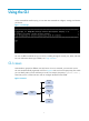
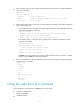
Using the CLI At the command-line interface (CLI), you can enter text commands to configure, manage, and monitor your device. Figure 1 CLI example You can use different methods to log in to the CLI, including through the console port, Telnet, and SSH. For more information about login methods, see "Login overview." CLI views Commands are grouped in different views by function. To use a command, you must enter its view. CLI views are hierarchically organized, as shown in Figure 2.
You are placed in user view immediately after you log in to the CLI. The user view prompt is , where Device-name indicates the device name. The device name is Sysname by default. You can change it by using the sysname command. In user view, you can do the following: • Perform basic operations including display, debug, file management, FTP, Telnet, clock setting, and reboot. • Enter system view. The system view prompt is [Device-name].
• Enter a question mark at a view prompt to display the first keyword of every command available in the view. For example: ? User view commands: archive Archive configuration backup Backup the startup configuration file to a TFTP server boot-loader Set boot loader … • Enter a space and a question mark after a command keyword to display all available, subsequent keywords and arguments.
For example, the info-center enable command enables the information center. The undo info-center enable command disables the information center. Entering a command When you enter a command, you can do the following: • Use keys or hotkeys to edit the command line. • Use abbreviated keywords or keyword aliases. Editing a command line To edit a command line, use the keys listed in Table 1 or the hotkeys listed in Table 2. When you are finished, you can press Enter to execute the command.
Space. • A specific argument might have more requirements. For more information, see the relevant command reference. To enter a printable character, you can enter the character or its ASCII code (in the range of 32 to 126). Abbreviating commands You can enter a command line quickly by entering incomplete keywords that uniquely identify the complete command. In user view, for example, commands starting with an s include startup saved-configuration and system-view.
Configuring and using command hotkeys The system defines the hotkeys shown in Table 2 and provides five configurable command hotkeys. Pressing a command hotkey is the same as entering a command. If a hotkey is also defined by the terminal software you are using to interact with the device, the terminal software definition takes effect. To configure a command hotkey: Step 1. Enter system view. Command Remarks system-view N/A By default: • Ctrl+G is assigned the display current-configuration command.
Hotkey Function Esc+F Moves the cursor forward one word. Esc+N Moves the cursor down one line. This hotkey is available before you press Enter. Esc+P Moves the cursor up one line. This hotkey is available before you press Enter. Esc+< Moves the cursor to the beginning of the clipboard. Esc+> Moves the cursor to the ending of the clipboard. Enabling redisplaying entered-but-not-submitted commands Your input might be interrupted by system information output.
Using the command history function The system automatically saves commands successfully executed by a login user to two command history buffers: • Command history buffer for the user line. • Command history buffer for all user lines. Table 4 Comparison between the two types of command history buffers Item Command history buffer for a user line Command history buffer for all user lines What kind of commands are stored in the buffer? Commands successfully executed by the current user of the user line.
Pausing between screens of output The system automatically pauses after displaying a screen if the output is too long to fit on one screen. You can use the keys described in "Output controlling keys" to display more information or stop the display. By default, up to 24 lines can be displayed on a screen. You can change the limit by using the screen-length screen-length command. For more information about this command, see Fundamentals Command Reference.
# Display information about VLAN 999, numbering each output line. display vlan 999 | by-linenum 1: VLAN ID: 999 2: VLAN type: Static 3: Route interface: Configured 4: IP address: 192.168.2.1 5: Subnet mask: 255.255.255.
Characters \N [] Meaning Examples Matches the preceding strings in parentheses, with the Nth string repeated once. Matches a single character in the brackets. "(string)\1" matches a string containing "stringstring". "(string1)(string2)\2" matches a string containing "string1string2string2". "(string1)(string2)\1\2" matches a string containing " string1string2string1string2". "[16A]" matches a string containing 1, 6, or A; "[1-36A]" matches a string containing 1, 2, 3, 6, or A (- is a hyphen).
Characters Meaning Examples \ Escape character. If a special character listed in this table follows \, the specific meaning of the character is removed. "\\" matches a string containing "\", "\^" matches a string containing "^", and "\\b" matches a string containing "\b". For example: # Use | begin line in the display current-configuration command to match the first line of output that contains line to the last line of output.
Use one of the following methods to save the output from a display command: • Save the output to a separate file. Use this method if you want to use one file for a single display command. • Append the output to the end of a file. Use this method if you want to use one file for multiple display commands. To save the output from a display command to a file, use one of the following commands in any view: Task Command Save the output from a display command to a separate file.
Untagged ports: FortyGigE1/0/1 Viewing and managing the output from a display command effectively You can use the following measures in combination to filter and manage the output from a display command: • Numbering each output line from a display command • Filtering the output from a display command • Saving the output from a display command to a file To use multiple measures to view and manage the output from a display command effectively, execute the following command in any view: Task Command V
Login overview The first time you access the device, you can log in to the CLI of the device through the console port. After login, you can change console login parameters, or configure other access methods, including Telnet, SSH, and SNMP. The device supports the FIPS mode that complies with NIST FIPS 140-2 requirements. Support for features, commands, and parameters might differ in FIPS mode and non-FIPS mode. For more information about FIPS mode, see Security Configuration Guide.
Logging in through the console port for the first device access The first time you access the device, you can only log in to the CLI through the console port. To log in through the console port, prepare a console terminal (for example, a PC) and make sure the console terminal has a terminal emulation program, for example, HyperTerminal in Windows XP. To log in through the console port: 1. Connect the DB-9 female connector of the console cable to the serial port of the PC. 2.
e. Select System Tools > Device Manager from the navigation tree. f. Select Ports (COM & LPT) from the right pane.
Figure 6 Setting the properties of the serial port 5. Power on the device and press Enter as prompted. Figure 7 Device CLI 6. At the default user view prompt , enter commands to configure the device or to view the running status of the device. To get help, enter ?.
Logging in to the CLI By default, you can log in to the CLI through the console port. After you log in, you can configure other login methods, including Telnet, and SSH. To prevent illegal access to the CLI and control user behavior, you can configure login authentication, assign user roles, configure command authorization and command accounting, and use ACLs to filter unauthorized logins.
A relative number uniquely identifies a user line among all user lines that are the same type. The number format is user line type + number. Both the types of user lines are numbered starting from 0 and incrementing by 1. For example, the first VTY line is VTY 0. Login authentication modes You can configure login authentication to prevent illegal access to the device CLI. In non-FIPS mode, the device supports the following login authentication modes: • None—Disables authentication.
Telnet login is not supported in FIPS mode. Logging in through the console port locally You can connect a terminal to the console port of the device to log in and manage the device, as shown in Figure 8. For the login procedure, see "Logging in through the console port for the first device access." Figure 8 Logging in through the console port By default, console login is enabled and does not require authentication.
Step Command Remarks 3. Disable authentication. authentication-mode none By default, authentication is disabled for the AUX line. 4. Assign a user role. user-role role-name By default, an AUX line user is assigned the user role network-admin. The next time you attempt to log in through the console port, you do not need to provide any username or password. Configuring password authentication for console login Step 1. Enter system view. Command Remarks system-view N/A Use either command.
Step Command Remarks Use either command. A setting in user line view is applied only to the user line. A setting in user line class view is applied to all user lines of the class. • To enter AUX line view: Enter AUX line view or class view. 2. line aux first-number [ last-number ] • To enter AUX line class view: line class aux Enable scheme authentication. 3. A non-default setting in either view takes precedence over a default setting in the other view.
Step Command Remarks Use either command. A setting in user line view is applied only to the user line. A setting in user line class view is applied to all user lines of the class. • To enter AUX line view: 2. Enter AUX line view or class view. line aux first-number [ last-number ] • To enter AUX line class view: line class aux A non-default setting in either view takes precedence over a default setting in the other view.
Step Command Remarks By default, the terminal display type is ANSI. 10. Specify the terminal display type. terminal type { ansi | vt100 } 11. Set the maximum number of lines to be displayed on a screen. screen-length screen-length 12. Set the size of the command history buffer. history-command max-size value The device supports two terminal display types: ANSI and VT100. HP recommends that you set the display type to VT100 on both the device and the configuration terminal.
Task Remarks (Optional.) Setting the maximum number of concurrent Telnet users N/A (Optional.) Setting the DSCP value for outgoing Telnet packets N/A (Optional.) Configuring common VTY line settings N/A The Telnet login configuration is effective only for users who log in after the configuration is completed. Disabling authentication for Telnet login Step Command Remarks 1. Enter system view. system-view N/A 2. Enable Telnet server.
Figure 9 Telnetting to the device without authentication Configuring password authentication for Telnet login Step Command Remarks 1. Enter system view. system-view N/A 2. Enable Telnet server. telnet server enable By default, the Telnet server function is disabled. Use either command. A setting in user line view is applied only to the user line. A setting in user line class view is applied to all user lines of the class. • To enter VTY line view: 3. Enter VTY line view or class view.
Step 6. (Optional.) Assign a user role. Command Remarks user-role role-name By default, a VTY line user is assigned the user role network-operator. The next time you attempt to Telnet to the device, you must provide the configured login password, as shown in Figure 10. If the maximum number of login users has been reached, your login attempt fails and the message "All user lines are used, please try later!" appears.
Step Command Remarks By default, password authentication is enabled for VTY lines. 4. Enable scheme authentication. authentication-mode scheme In VTY line view, this command is associated with the protocol inbound command. If you specify a non-default value for only one of the two commands in VTY line view, the other command uses the default setting, regardless of the setting in VTY line class view. To use scheme authentication, you must also configure login authentication methods in ISP domain view.
Setting the DSCP value for outgoing Telnet packets The DSCP value is carried in the ToS/Traffic class field of an IP packet, and it indicates the transmission priority of the packet. To set the DSCP value for outgoing Telnet packets: Step Command Remarks 1. Enter system view. system-view N/A 2. Set the DSCP value for outgoing Telnet packets. telnet server dscp dscp-value By default, the DSCP value is 48.
Step Command Remarks By default, both Telnet and SSH are supported. This configuration is effective only for users who log in to the user lines after the configuration is completed. 4. Specify the protocols for the user lines to support. protocol inbound { all | ssh | telnet } 5. Define a shortcut key for terminating tasks. escape-key { character | default } By default, pressing Ctrl+C terminates a task. 6. Specify the terminal display type.
Step 1. Enter system view. Command Remarks system-view N/A 2. (Optional.) Specify the source IPv4 address or source interface for outgoing Telnet packets. telnet client source { interface interface-type interface-number | ip ip-address } By default, no source IPv4 address or source interface is specified, and the primary IPv4 address of the outbound interface is used as the source address for outgoing Telnet packets. 3. Exit to user view. quit N/A 4.
Step Command Remarks • In non-FIPS mode: 4. (Optional.) Create an SSH user and specify the authentication mode. ssh user username service-type stelnet authentication-type { password | { any | password-publickey | publickey } assign publickey keyname } • In FIPS mode: By default, no SSH user is configured on the device. ssh user username service-type stelnet authentication-type { password | password-publickey assign publickey keyname } Use either command.
Step Command Remarks In non-FIPS mode, both Telnet and SSH are supported by default. In FIPS mode, SSH is supported by default. • In non-FIPS mode: 7. (Optional.) Specify the protocols for the user lines to support. protocol inbound { all | ssh | telnet } • In FIPS mode: protocol inbound ssh This configuration takes effect only for users who log in to the user lines after the configuration is completed. In VTY line view, this command is associated with the authentication-mode command.
Displaying and maintaining CLI login Execute display commands in any view and the other commands in user view. Task Command Remarks Display online CLI user information. display users [ all ] N/A Display user line information. display line [ num1 | { aux | vty } num2 ] [ summary ] N/A Display the source IPv4 address or interface configured for the device to use for outgoing Telnet packets when serving as a Telnet client.
Accessing the device through SNMP You can run SNMP on an NMS to access the device MIB and perform Get and Set operations to manage and monitor the device. Figure 14 SNMP access diagram Get/Set requests NMS Get/Set responses and Traps MIB Agent The device supports SNMPv1, SNMPv2c, and SNMPv3, and can work with various network management software products, including IMC. However, the device and the NMS must use the same SNMP version.
Configuring SNMPv1 or SNMPv2c access Step Command Remarks 1. Enter system view. system-view N/A 2. Enable the SNMP agent. snmp-agent By default, the SNMP agent is disabled. By default, the device has four views, all of which are named ViewDefault: • View 1 includes MIB subtree 3. (Optional.) Create or update MIB view information. snmp-agent mib-view { excluded | included } view-name oid-tree [ mask mask-value ] iso. • View 2 does not include subtree snmpUsmMIB.
FIPS compliance The device supports the FIPS mode that complies with NIST FIPS 140-2 requirements. Support for features, commands, and parameters might differ in FIPS mode and non-FIPS mode. For more information about FIPS mode, see Security Configuration Guide. Telnet and HTTP are not supported in FIPS mode. Controlling Telnet/SSH logins Use basic ACLs (2000 to 2999) to filter Telnet and SSH logins by source IP address.
Figure 15 Network diagram Configuration procedure # Configure an ACL to permit packets sourced from Host A and Host B. system-view [Sysname] acl number 2000 match-order config [Sysname-acl-basic-2000] rule 1 permit source 10.110.100.52 0 [Sysname-acl-basic-2000] rule 2 permit source 10.110.100.46 0 [Sysname-acl-basic-2000] quit # Apply the ACL to filter Telnet logins.
Step Command Remarks • SNMP community: snmp-agent community { read | write } [ simple | cipher ] community-name [ mib-view view-name ] [ acl acl-number ] * • SNMPv1/v2c group: snmp-agent group { v1 | v2c } group-name [ read-view view-name ] [ write-view view-name ] [ notify-view view-name ] [ acl acl-number ] * 2. Apply the ACL to an SNMP community, group, or user.
[Sysname-acl-basic-2000] rule 2 permit source 10.110.100.46 0 [Sysname-acl-basic-2000] quit # Associate the ACL with the SNMP community and the SNMP group. [Sysname] snmp-agent community read aaa acl 2000 [Sysname] snmp-agent group v2c groupa acl 2000 [Sysname] snmp-agent usm-user v2c usera groupa acl 2000 Configuring command authorization By default, commands are available for a user depending only on that user's user roles.
Step Command Remarks By default, authentication is disabled for the AUX line and password authentication is enabled for the VTY line. 3. Enable scheme authentication. authentication-mode scheme In VTY line view, this command is associated with the protocol inbound command. If you specify a non-default value for only one of the two commands in VTY line view, the other command uses the default setting, regardless of the setting in VTY line class view.
[Device-line-vty0-63] authentication-mode scheme # Enable command authorization for the user lines. [Device-line-vty0-63] command authorization [Device-line-vty0-63] quit # Configure an HWTACACS scheme that does the following: • Uses the HWTACACS server at 192.168.2.20:49 for authentication and authorization. In this example, the HWTACACS server provides authentication and authorization services at port 49. • Uses the shared key expert.
Configuring RBAC Role based access control (RBAC) controls user access to commands and resources based on user role. This chapter describes the basic idea of RBAC and guides you through the RBAC configuration procedure. Overview On devices that support multiple users, RBAC is used to assign command and resource access permissions to user roles that are created for different job functions. Users are given permission to access a set of commands and resources based on their user roles.
A user role can access the set of permitted commands specified in its rules. The user role rules include predefined (identified by sys-n) and user-defined user role rules. • If two user-defined rules of the same type conflict, the one with higher number takes effect. For example, if rule 1 permits the ping command, rule 2 permits the tracert command, and rule 3 denies the ping command, the user role can use the tracert command but not the ping command.
User role name Permissions • level-0—Has access to diagnostic commands, including ping, quit, ssh2, super, system-view, telnet, and tracert. Level-0 access rights are configurable. • level-1—Has access to the display commands (except display history-command all) of all features and resources in the system, in addition to all access rights of the user role level-0. Level-1 access rights are configurable. • level-2 to level-8, and level-10 to level-14—Have no access rights by default.
FIPS compliance The device supports the FIPS mode that complies with NIST FIPS 140-2 requirements. Support for features, commands, and parameters might differ in FIPS mode and non-FIPS mode. For more information about FIPS mode, see Security Configuration Guide. Configuration task list Tasks at a glance (Required.) Creating user roles (Required.) Configuring user role rules (Optional.) Configuring feature groups (Optional.) Changing resource access policies (Optional.) Assigning user roles (Optional.
If two user-defined rules of a user role conflict, the one with a higher ID takes effect. For level-0 to level-14 user roles, if a predefined user role rule and a user-defined user role rule conflict, the user-defined user role rule takes effect. Any rule modification, addition, or removal for a user role takes effect only on users who are logged in with the user role after the change. To configure rules for a user role: Step Command Remarks 1. Enter system view. system-view N/A 2.
Changing resource access policies Every user role has one interface policy and VLAN policy. By default, these policies permit user roles to access any interface and VLAN. You can change the policies of user-defined user roles and the predefined level-n user roles to limit their access to interfaces and VLANs. A changed policy takes effect only on users who are logged in with the user role after the change. Changing the interface policy of a user role Step Command Remarks 1. Enter system view.
Enabling the default user role function An AAA authentication user must have at least one user role to log in to the device. The default user role function assigns the network-operator user role to a local or remote AAA authenticated user if the AAA server has not authorized the user to use any user roles. Without the function, AAA authenticated users cannot access the system if they have no user role authorization.
Step Command Authorize the user to have a user role. 3. Remarks authorization-attribute user-role role-name Repeat this step to assign the user to up to 64 user roles. By default, network-operator is assigned to local users created by a network-admin or level-15 user. Assigning user roles to non-AAA authentication users on user lines Specify user roles for the following two types of login users on the user lines: • Users who use password authentication or no authentication.
• To enable users to obtain temporary user roles, you must configure user role authentication. Table 10 describes the available authentication modes and configuration requirements. • Local password authentication is available for all user roles, but remote AAA authentication is available only for level-n user roles. { { • If HWTACACS authentication is used, use a user account that has the target user role level or a user role level higher than the target user role.
Configuring user role authentication Step Command Remarks 1. Enter system view. system-view N/A 2. Set an authentication mode. super authentication-mode { local | scheme } * By default, local-only authentication applies. • In non-FIPS mode: 3. Set a local authentication password for a user role. super password [ role rolename ] [ { hash | simple } password ] • In FIPS mode: super password [ role rolename ] Use this step for local password authentication.
RBAC configuration examples RBAC configuration example for local AAA authentication users Network requirements The switch in Figure 18 performs local AAA authentication for the Telnet user at 192.168.1.58. This Telnet user has the username user1@bbb and is assigned the user role role1. Configure role1 to have the following permissions: • Executes the read commands of any feature. • Configures no VLANs except VLANs 10 to 20.
[Switch-role-role1] vlan policy deny [Switch-role-role1-vlanpolicy] permit vlan 10 to 20 [Switch-role-role1-vlanpolicy] quit [Switch-role-role1] quit # Create a device management user named user1 and enter its view. [Switch] local-user user1 class manage # Set a plaintext password aabbcc for the user. [Switch-luser-manage-user1] password simple aabbcc # Set the service type to Telnet. [Switch-luser-manage-user1] service-type telnet # Assign role1 to the user.
• Performs read and write commands of the features arp and radius. • Has no access to read commands of the feature acl. • Configures VLANs 1 to 20 and interfaces FortyGigE 1/0/1 to FortyGigE 1/0/24. The switch and the FreeRADIUS server use the shared key expert and authentication port 1812. The switch delivers usernames with their domain names to the server. Figure 19 Network diagram Configuration procedure Make sure the settings on the switch and the RADIUS server match. 1.
IMPORTANT: Because RADIUS user authorization information is piggybacked in authentication responses, the authentication and authorization methods must use the same RADIUS scheme. [Switch] domain bbb [Switch-isp-bbb] authentication login radius-scheme rad [Switch-isp-bbb] authorization login radius-scheme rad [Switch-isp-bbb] quit # Create the feature group fgroup1. [Switch] role feature-group name fgroup1 # Add the features arp and radius to the feature group.
Verifying the configuration # Telnet to the switch, and enter the username and password to access the switch. (Details not shown.) # Verify that you can use all commands available in ISP view. system-view [Switch] domain abc [Switch-isp-abc] authentication login radius-scheme abc [Switch-isp-abc] quit # Verify that you can use all read and write commands of the features radius and arp. Take radius as an example. [Switch] radius scheme rad [Switch-radius-rad] primary authentication 2.2.2.
Figure 20 Network diagram Configuration procedure 1. Configure the switch: # Assign an IP address to VLAN-interface 2, the interface connected to the Telnet user. system-view [Switch] interface vlan-interface 2 [Switch-Vlan-interface2] ip address 192.168.1.70 255.255.255.0 [Switch-Vlan-interface2] quit # Assign an IP address to VLAN-interface 3, the interface connected to the HWTACACS server. [Switch] interface vlan-interface 3 [Switch-Vlan-interface3] ip address 10.1.1.2 255.255.255.
# Configure ISP domain bbb to use local authorization for login users. [Switch-isp-bbb] authorization login local # Apply the HWTACACS scheme hwtac to the ISP domain. [Switch-isp-bbb] authentication super hwtacacs-scheme hwtac [Switch-isp-bbb] quit # Create a device management user named test and enter its view. Set the service type to Telnet, and set the password to aabbcc.
Figure 21 Configuring advanced TACACS+ settings Verifying the configuration 1. Telnet to the switch, and enter the username test@bbb and password aabbcc to access the switch. Verify that you have access to diagnostic commands. telnet 192.168.1.70 Trying 192.168.1.70 ... Press CTRL+K to abort Connected to 192.168.1.59 ... ****************************************************************************** * Copyright (c) 2010-2013 Hewlett-Packard Development Company, L.P.
ssh2 Establish a secure shell client connection super Switch to a user role system-view Enter the System View telnet Establish a telnet connection tracert Tracert function 2. Obtain the level-3 user role: # Use the super password to obtain the level-3 user role. When the system prompts for a username and password, enter the username test@bbb and password enabpass.
Login attempts by RADIUS users always fail Symptom Attempts by a RADIUS user to log in to the network access device always fail, even though the network access device and the RADIUS server can communicate with one another and all AAA settings are correct. Analysis RBAC requires that a login user have at least one user role. If the RADIUS server does not authorize the login user to use any user role, the user cannot log in to the device.
Configuring FTP File Transfer Protocol (FTP) is an application layer protocol based on the client/server model. It is used to transfer files from one host to another over an IP network. FTP server uses TCP port 20 to transfer data and TCP port 21 to transfer control commands. For more information about FTP, see RFC 959. FTP supports the following transfer modes: • Binary mode—Used to transfer image files, such as .app, .bin, and .btm files. This mode is also called "flow mode.
Configuring basic parameters Step Command Remarks 1. Enter system view. system-view N/A 2. Enable the FTP server. ftp server enable By default, the FTP server is disabled. 3. (Optional.) Use an ACL to control access to the FTP server. ftp server acl acl-number By default, no ACL is used for access control. The default idle-timeout interval is 30 minutes. 4. (Optional.) Configure the idle-timeout interval.
Manually releasing FTP connections Task Command Manually release FTP connections. free ftp user username Displaying and maintaining the FTP server Execute display commands in any view. Task Command Display FTP server configuration and status information. display ftp-server Display detailed information about online FTP users.
[Sysname-luser-manage-abc] authorization-attribute user-role network-admin work-directory flash:/ # Assign the service type FTP to the user. [Sysname-luser-manage-abc] service-type ftp [Sysname-luser-manage-abc] quit NOTE: If the password control feature is configured, the password must meet the password requirements defined by the feature. For more information, see Security Configuration Guide. # Enable the FTP server.
ftp> put temp.bin # Exit FTP. ftp> bye FTP server configuration example in IRF mode Network requirements As shown in Figure 24, a two-chassis IRF fabric has two MPUs. The global active MPU is in slot 0 of the master. The global standby MPU is in slot 0 of the subordinate member. On the device, create a local user account with the username abc and password 123456 and enable the FTP server function. From the PC, use the user account to log in to the FTP server and do the following: • Upload the file temp.
NOTE: If the password control feature is configured, the password must meet the password requirements defined by the feature. For more information, see Security Configuration Guide. # Enable the FTP server. [Sysname] ftp server enable [Sysname] quit 3. Perform FTP operations from the FTP client: # Log in to the FTP server at 1.1.1.1 using the username abc and password 123456. c:\> ftp 1.1.1.1 Connected to 1.1.1.1. 220 FTP service ready. User(1.1.1.1:(none)):abc 331 Password required for abc.
Step Command Remarks • (Method 1) Log in to the FTP server Log in to the FTP server. 4. directly in user view: ftp [ ftp-server [ service-port ] [ dscp dscp-value | source { interface interface-type interface-number | ip source-ip-address } ] ] * • (Method 2) Log in to the FTP server in FTP client view: a. ftp Use either method. The source IP address specified in the ftp command takes precedence over the one set by the ftp client source command. b.
Task Command Remarks • Display the detailed Display directory or file information on the FTP server. information of a directory or file on the FTP server: dir [ remotefile [ localfile ] ] • Display the name of a N/A directory or file on the FTP server: ls [ remotefile [ localfile ] ] Delete the specified file on the FTP server permanently. delete remotefile N/A Set the file transfer mode to ASCII. ascii The default file transfer mode is binary. Set the file transfer mode to binary.
Maintaining and troubleshooting the FTP connection Task Command Remarks Display FTP commands on the FTP server. rhelp N/A Display FTP commands help information on the FTP server. rhelp protocol-command N/A Display FTP server status. rstatus N/A Display detailed information about a directory or file on the FTP server. rstatus remotefile N/A Display FTP connection status. status N/A Display the system information of the FTP server.
Task Command Display source IP address information on the FTP client. display ftp client source FTP client configuration example in standalone mode Network requirements As shown in Figure 25, a PC acts as the FTP server. An FTP user account with the username abc and password 123456 is configured on the FTP server. Use the device as the FTP client to log in to the FTP server and do the following: • Download the file temp.bin from the PC to the device. • Upload the configuration file startup.
# Set the file transfer mode to ASCII. Upload the configuration file startup.cfg from the device to the PC for backup. ftp> ascii 200 TYPE is now ASCII ftp> put startup.cfg back-startup.cfg local: startup.cfg remote: back-startup.cfg 150 Connecting to port 47461 226 File successfully transferred 3494 bytes sent in 5.646 seconds (618.00 kbyte/s) ftp> bye 221-Goodbye. You uploaded 2 and downloaded 2 kbytes. 221 Logout.
331 Give me your password, please Password: 230 Logged in successfully Remote system type is MSDOS. 200 Type is Image (Binary) # Download the file temp.bin from the PC to the Flash root directory of the global active MPU. ftp> get temp.bin local: temp.bin remote: temp.bin 150 Connecting to port 47457 226 File successfully transferred 23951480 bytes received in 95.399 seconds (251.0 kbyte/s) # Download the file temp.bin from the PC to the Flash root directory of the global standby MPU. ftp> get temp.
Configuring TFTP Trivial File Transfer Protocol (TFTP) is a simplified version of FTP for file transfer over secure reliable networks. TFTP uses UDP port 69 for data transmission. In contrast to TCP-based FTP, TFTP does not require authentication or complex message exchanges, and is easier to deploy. TFTP is suited for reliable network environments. The device can only operate as a TFTP client. You can upload a file from the device to the TFTP server or download a file from the TFTP server to the device.
Step 5. Command Download or upload a file in an IPv4 network. Remarks tftp tftp-server { get | put | sget } source-filename [ destination-filename ] [ dscp dscp-value | source { interface interface-type interface-number | ip source-ip-address } ] * 77 The source IP address specified in this command takes precedence over the one set by the tftp client source command. Use this command in user view.
Managing the file system This chapter describes how to manage the device's file system, including the storage media, directories, and files. IMPORTANT: • Before managing storage media, files, and directories, make sure you know the possible impacts. • A file or directory whose name starts with a period (.) is considered a hidden file or directory. Do not give a common file or directory a name that starts with a period. • Some system files and directories are hidden.
Format Description Example Specifies a file in a specific storage medium. The drive argument represents the storage medium name. drive:/[path]/file-name A storage medium is typically flash or usb0. flash:/test/a.cfg indicates a file named a.cfg in the test folder in the root directory of the MPU. To view the correspondence between the MPU and its slot number, use the display device command.
• Display directory and file information. • Display file contents. • Rename, copy, move, remove, restore, delete, compress, decompress, archive, and extract files. • Calculate the digests of files for file integrity verification. You can create a file by copying, downloading, or using the save command. For more information about downloading a file, see "Configuring FTP" and "Configuring TFTP." For more information about the save command, see Fundamentals Command Reference.
Task Command Move a file. move fileurl-source fileurl-dest Compressing/decompressing a file Perform the following tasks in user view: Task Command Compress a file. gzip filename Decompress a file. gunzip filename Archiving/extracting files Perform the following tasks in user view: Task Command Archive files. tar create [ gz ] archive-file fileurl-dest [ verbose ] source fileurl-source-list&<1-5> Extract files.
Deleting files from the recycle bin The device supports multiple storage media. Each storage medium has a recycle bin of its own. The device supports multiple storage media. If a storage medium is not partitioned, it has a recycle bin of its own. If a storage medium is partitioned, each partition has its own recycle bin. A recycle bin is a folder named .trash in the root directory of the storage medium or partition.
Task Command Display directory or file information. dir [ /all ] [ file-url | /all-filesystems ] Displaying the current working directory Perform this task in user view. Task Command Display the current working directory. pwd Changing the current working directory Perform this task in user view. Task Command Change the current working directory. cd { directory | .. | / } Creating a directory Perform this task in user view. Task Command Create a directory.
If you remove a storage medium while a folder or file on the storage medium is being accessed, the device might not recognize the storage medium when you reinstall it. To reinstall this kind of a storage medium, complete one of the following tasks: • If you were accessing a folder on the storage medium, change the current directory. • If you were accessing a file on the storage medium, close the file.
Restrictions and guidelines To mount/unmount a partitioned storage medium, you must mount/unmount all the partitions individually, instead of mounting/unmounting the medium as a whole. To unmount a USB disk, make sure the system has recognized the USB disk and the USB disk LED is not blinking. Otherwise, the USB interface or USB disk might be damaged. Before unmounting a storage medium, make sure no other users are accessing the medium. Otherwise, the unmount operation fails.
Configuration procedure Perform this task in user view. Task Command Remarks Partition a storage medium. fdisk medium-name [ partition-number ] By default, only one partition usb0:/ is available on a USB disk. Setting the operation mode for files and folders The device supports the following file and folder operation modes: • alert—The system prompts for confirmation when your operation might cause problems such as file corruption and data loss.
Managing configuration files You can use the CLI or the BootWare menus to manage configuration files. This chapter explains how to manage configuration files from the CLI. Overview A configuration file saves a set of commands for configuring software features on the device. You can save any configuration to a configuration file so they can survive a reboot. You can also back up configuration files to a host for future use.
Running configuration The running configuration includes startup settings that have not been changed and new settings you made. The running configuration is stored in the memory and is cleared at a device reboot or power off. To use the running configuration after a power cycling or reboot, save it to a configuration file. To view the running configuration, use the display current-configuration command. The displayed configuration does not include parameters that use initial settings.
b. If you have not specified a main startup configuration file, or the specified main startup configuration file is not available, the device searches for the backup startup configuration file. c. If you have not specified a backup startup configuration file, or the specified backup startup configuration file is not available, the device starts up with the default configuration file (called "factory defaults"). If a parameter is not included in the default configuration file, its initial setting is used.
interface FortyGigE1/0/1 port link-mode route ip address 1.1.1.1 255.255.255.0 # FIPS compliance The device supports the FIPS mode that complies with NIST FIPS 140-2 requirements. Support for features, commands, and parameters might differ in FIPS mode and non-FIPS mode. For more information about FIPS mode, see Security Configuration Guide.
Task Command Remarks • In standalone mode: Save the running configuration to a configuration file. save file-url [ all | slot slot-number ] • In IRF mode: N/A save file-url [ all | chassis chassis-number slot slot-number ] If you execute the save [ safely ] command without specifying any other keyword, the command saves the configuration to the main startup configuration file. Save the running configuration to a configuration file and specify the file as the next-startup configuration file.
The undo startup saved-configuration command changes the attribute of the main or backup next-startup configuration file to NULL instead of deleting the file. • To specify a next-startup configuration file, perform the following task in user view: Task Command Remarks By default, no configuration file is specified for the next startup. Specify the next-startup configuration file.
You have read and write permissions. • To restore the main next-startup configuration file from a TFTP server: Step 1. Restore the main next-startup configuration file from a TFTP server in user view. 2. (Optional.) Verify that the specified configuration file has been set as the main next-startup configuration file. Command Remarks restore startup-configuration from src-addr src-filename This command is not supported in FIPS mode.
Task Command Display the running configuration. display current-configuration [ configuration [ module-name ] | interface [ interface-type [ interface-number ] ] ] Display the factory defaults. display default-configuration Display the contents of the configuration file for the next system startup. display saved-configuration Display names of the configuration files used at this startup and the next startup. display startup Display the valid configuration in the current view.
Upgrading software This chapter describes types of software and how to upgrade software from the CLI. For a comparison of all software upgrade methods, see "Upgrade methods." Overview Software upgrade enables you to have new features and fix bugs. Before performing an upgrade, use the release notes for the new software version to verify software and hardware compatibility and evaluate upgrade impacts. NOTE: The switch has one built-in MPU. The slot number of this MPU is fixed at 0.
Software file naming conventions Software image file names use the chassis-comware version-image type-release format, for example, 7904-CMW710-SYSTEM-R2109.bin and 7904-CMW710-BOOT-R2109.bin. This document uses boot.bin and system.bin as boot and system image file names. Comware image redundancy and loading procedure You can specify two sets of Comware software images: one main and one backup. The system always attempts to start up with the main images.
System startup process Upon power-on, the BootWare image runs to initialize hardware, and then the startup software images run to start up the entire system, as shown in Figure 30. Figure 30 System startup process Upgrade methods Upgrading method Software types Upgrading from the CLI • BootWare image • Comware images (excluding patches) Remarks This method is disruptive. You must reboot the entire device to complete the upgrade. Use this method when the device cannot start up correctly.
1. Download the upgrade software image file. 2. (Optional.) Preload the BootWare image to the BootWare. If a BootWare upgrade is required, you can perform this task to shorten the subsequent upgrade time. This task helps avoid upgrade problems caused by unexpected electricity failure. If you skip this task, the device upgrades the BootWare automatically when it upgrades the startup software images. The BootWare image preloaded into the BootWare does not affect the device running status. 3.
Step Command Remarks By default, this function is enabled. 2. (Optional.) Enable BootWare image validity check. bootrom-update security-check enable 3. Return to user view. quit 4. (Optional.) Back up the current BootWare image in the Normal area of BootWare to the Backup area. This function examines the image for wrong file type, file corruption, and hardware incompatibility. HP recommends enabling it to ensure a successful upgrade.
Step 2. Save the running configuration. Command Remarks save This step makes sure any configuration you have made can survive a reboot. 3. Reboot the device. reboot At startup, the MPU reads the preloaded BootWare image to RAM, loads the startup images in the file, and sets the images as both current software images and startup software images. 4. (Optional.) Verify the software image settings.
Step Command Remarks When you use method 3, make sure you understand the following requirements and upgrade results: • Method 1: • If the global active MPU started up with main startup images, its main startup images are synchronized to the standby MPU. This synchronization occurs regardless of whether any change has been made to this set of startup images. boot-loader file ipe-filename chassis chassis-number slot slot-number { backup | main } • Method 2: 2.
Step Command Remarks In standalone mode: • Use the BootWare image in the Backup area of BootWare for a replacement: bootrom restore slot slot-number-list • Use the BootWare image in a 1. Replace the BootWare image in the Normal area of BootWare.
Software upgrade examples Software upgrade example (for standalone mode) Network requirements As shown in Figure 31, use the file 7904.ipe to upgrade software images for the device. Figure 31 Network diagram TFTP server TFTP client 1.1.1.1/24 2.2.2.2/24 Internet Device Configuration procedure # Configure IP addresses and routes. Make sure the device and the TFTP server can reach each other. (Details not shown.) # Complete TFTP settings on both the device and the TFTP server. (Details not shown.
Figure 32 Network diagram Master (Member ID = 1) Internet Subordinate (Member ID = 2) IRF link IRF 1.1.1.1/24 2.2.2.2/24 TFTP server Configuration procedure # Configure IP addresses and routes. Make sure the device and the TFTP server can reach each other. (Details not shown.) # Complete TFTP settings on both the device and the TFTP server. (Details not shown.) # Display information about the current software images. display version # Use TFTP to download the image file 7904.
Managing the device This chapter describes how to monitor the operating status of the device, configure the running parameters (such as the device name, system time, and the temperature alarm thresholds), and reboot the device. You can perform the configuration tasks in this chapter in any order. The switch has one built-in MPU. The slot number of this MPU is fixed at 0. Unless otherwise stated, the term "card" in this document refers to both the MPU and LPUs.
Step Set the UTC time. 1. Command Remarks clock datetime time date By default, the factory default UTC time is used. Use this command in user view. 2. Enter system view. system-view N/A 3. Set the local time zone. clock timezone zone-name { add | minus } zone-offset The default local time zone is the UTC time zone. 4. Set the daylight saving time. clock summer-time name start-time start-date end-time end-date add-time By default, daylight saving time is disabled.
Step 2. Enable displaying the copyright statement. Command Remarks copyright-info enable By default, this function is enabled. Configuring banners Banners are messages that the system displays when a user logs in. Banner types The system supports the following banners: • Legal banner—Appears after the copyright statement. To continue login, the user must enter Y or press Enter. To quit the process, the user must enter N. Y and N are case insensitive.
system-view [System] header shell A Please input banner content, and quit with the character 'A'. Have a nice day. Please input the password.A { Method 3—After you type the last command keyword, type the start delimiter and part of the banner and press Enter. At the system prompt, enter the rest of the banner and end the last line with the same delimiter. For example, you can configure the banner "Have a nice day. Please input the password.
• Schedule a reboot at the CLI, so the device automatically reboots at the specified time or after the specified period of time. • Power off and then power on the device. This method might cause data loss, and is the least-preferred method. Using the CLI, you can reboot the device from a remote host. Configuration guidelines • In standalone mode, the automatic reboot configuration is canceled if an active/standby switchover occurs.
You can configure a one-time schedule or a periodic schedule. A one-time schedule is not saved to the configuration file and is lost when the device reboots. A periodic schedule is saved to the startup configuration file and is automatically executed periodically. Configuration guidelines • To make sure a task schedule can be executed as expected, reconfigure the system time or configure NTP after you reboot the device.
Step Command Remarks • Specify the execution date and time: time at time date 8. Specify an execution time table for the one-time schedule. • Specify the execution days and time: time once at time [ month-date month-day | week-day week-day&<1-7> ] • Specify the execution delay time: time once delay time Configure one command as required. By default, no execution time is specified for a schedule.
Schedule configuration example Network requirements To save energy, configure the device to enable interfaces FortyGigE 1/0/1 and FortyGigE 1/0/2 at 8:00 a.m. every Monday through Friday and disable the interfaces at 18:00 every Monday through Friday. Figure 33 Network diagram Scheduling procedure # Enter system view. system-view # Configure a job for disabling interface FortyGigE 1/0/1.
[Sysname-job-start-FortyGigE1/0/2] command 3 undo shutdown [Sysname-job-start-FortyGigE1/0/2] quit # Configure a periodic schedule for enabling the interfaces at 8:00 a.m. every Monday through Friday.
start-FortyGigE1/0/2 Successful Schedule name : STOP-pc1/pc2 Schedule type : Run on every Mon Tue Wed Thu Fri at 18:00:00 Start time : Wed Sep 28 18:00:00 2011 Last execution time : Wed Sep 28 18:00:00 2011 Last completion time : Wed Sep 28 18:00:01 2011 Execution counts : 1 ----------------------------------------------------------------------Job name Last execution status shutdown-FortyGigE1/0/1 Successful shutdown-FortyGigE1/0/2 Successful # Display schedule log information.
--------------------------------- Job output ----------------------------------system-view System View: return to User View with Ctrl+Z. [Sysname]interface fortygige 1/0/2 [Sysname-FortyGigE1/0/2]shutdown Disabling password recovery capability Password recovery capability controls console user access to the device configuration and SDRAM from BootWare menus. This feature also determines the method for handling console login password loss.
To monitor the CPU usage: Step 1. Enter system view. Command Remarks system-view N/A • In standalone mode: 2. Enable the CPU usage monitoring function. monitor cpu-usage enable [ slot slot-number ] • In IRF mode: monitor cpu-usage enable [ chassis chassis-number slot slot-number ] By default, the CPU usage monitoring function is enabled. • In standalone mode: 3. Configure the interval at which the device samples CPU usage statistics.
Setting memory alarm thresholds To ensure correct operation and improve memory utilization, the system monitors the amount of free memory space in real time. When a threshold is exceeded, the system generates an alarm notification or an alarm-removed notification and sends it to affected service modules or processes. As shown in Table 13 and Figure 34, the system supports the following thresholds: • Normal state threshold. • Minor alarm threshold. • Severe alarm threshold. • Critical alarm threshold.
Figure 34 Memory alarm notification and alarm-removed notification Free memory space Minor alarm-removed Normal Minor alarm Severe alarm-removed Minor Critical alarm-removed Severe alarm Severe Critical alarm Critical Time To set memory alarm thresholds: Step 1. Enter system view. Command Remarks system-view N/A • In standalone mode: memory-threshold [ slot slot-number ] minor minor-value severe severe-value critical critical-value normal normal-value 2. Set memory alarm thresholds.
Step Enter system view. 1. Command Remarks system-view N/A • In standalone mode: Configure the temperature alarm thresholds. 2. For the default settings, see Table 14. temperature-limit slot slot-number hotspot sensor-number lowlimit warninglimit [ alarmlimit ] The high-temperature alarming threshold must be higher than the high-temperature warning threshold. The high-temperature warning threshold must be higher than the low-temperature threshold.
Task Command Remarks Display the electrical label information of transceiver modules. display transceiver manuinfo interface [ interface-type interface-number ] This command cannot display information for some transceiver modules. Diagnosing transceiver modules The device provides the alarm and digital diagnosis functions for transceiver modules.
Task Command Display hardware information. display device [ flash ] [ slot slot-number [ subslot subslot-number ] | verbose ] Display the electronic label information of the device. display device manuinfo [ slot slot-number ] Display the electronic label information of a fan. display device manuinfo fan fan-id Display the electronic label information of a power supply. display device manuinfo power power-id Display the operating statistics for multiple feature modules.
Task Command Display hardware information. display device [ flash ] [ chassis chassis-number [ slot slot-number [ subslot subslot-number ] ] | verbose ] Display the electronic label information of the device. display device manuinfo [ chassis chassis-number [ slot slot-number ] ] Display the electronic label information of a fan. display device manuinfo chassis chassis-number fan fan-id Display the electronic label information of a power supply.
Using Python Python is an easy to learn, powerful programming language. It has efficient high-level data structures and a simple but effective approach to object-oriented programming. Python's elegant syntax and dynamic typing, together with its interpreted nature, make it an ideal language for scripting and rapid application development in many areas on most platforms. Comware V7 provides a built-in Python interpreter that supports the following items: • Python 2.7 commands. • Python 2.7 standard API.
Configuration procedure # Use a text editor on the PC to edit Python script test.py as follows: #!usr/bin/python import comware comware.Transfer('tftp', '192.168.1.26', 'main.cfg', 'flash:/main.cfg') comware.Transfer('tftp', '192.168.1.26', 'backup.cfg', 'flash:/backup.cfg') comware.CLI('startup saved-configuration flash:/main.cfg main ;startup saved-configuration flash:/backup.cfg backup') # Use TFTP to download the script to the device. tftp 192.168.1.26 get test.py # Execute the script.
Comware V7 extended Python API The Comware V7 extended Python API is compatible with the Python syntax. Importing and using the Comware V7 extended Python API To use the Comware V7 extended Python API, you must import the API to Python. Use either of the following methods to import and use the Comware V7 extended Python API: • Use import comware to import the entire API and use comware.API to execute an API. For example, to use the extended API Transfer to download file test.cfg from TFTP server 192.168.
Parameters command: Specifies the commands to be executed. To enter multiple commands, use a space and a semicolon (;) as the delimiter. To enter a command in a view other than user view, you must first enter the commands used to enter the view. For example, you must enter ’system-view ;local-user test class manage’ to execute the local-user test class manage command. do_print: Specifies whether to output the execution result: • True—Outputs the execution result. This value is the default.
Transfer class Transfer Use Transfer to download a file from a server. Syntax Transfer(protocol=‘’, host=‘’, source=‘’, dest=‘’, login_timeout=10, user=‘’, password=‘’) Parameters protocol: Specifies the protocol used to download a file: • ftp—Uses FTP. • tftp—Uses TFTP. • http—Uses HTTP. host: Specifies the IP address of the remote server. source: Specifies the name of the file to be downloaded from the remote server. dest: Specifies a name for the downloaded file.
[GCC 4.4.1] on linux2 Type "help", "copyright", "credits" or "license" for more information. >>> import comware >>> c = comware.Transfer('tftp', '1.1.1.1', 'test.cfg', 'flash:/test.cfg', user='', password='') >>> c.get_error() Sample output “Couldn’t connect to server” API get_self_slot get_self_slot Use get_self_slot to get the slot number of the MPU in standalone mode, or the slot number of the global active MPU in IRF mode.
• [ ]—The IRF fabric does not have a global standby MPU. • [[chassis-number,slot-number]]—The IRF fabric has only one global standby MPU. The chassis-number indicates the member ID of the subordinate switch. The slot-number indicates the slot number of the global standby MPU. • [[chassis-number1,slot-number1],[chassis-number2,slot-number2],...]—The IRF fabric has multiple global standby MPUs. Examples # In IRF mode, get the slot numbers of all global standby MPUs. python Python 2.7.
Using automatic configuration With the automatic configuration feature, the device can automatically obtain a set of configuration settings from some servers when it starts up without a configuration file. This feature simplifies network configuration, facilitates centralized management, and reduces maintenance workload.
{ A TFTP server IP address. { A DNS server IP address. For more information, see "Automatic-configuration parameter acquisition process." 3. After obtaining automatic configuration parameters, the device tries to download a configuration file from a TFTP server or an HTTP server. For more information, see "Configuration file acquisition process." 4. If the device obtains a configuration file, it deletes its temporary settings to restore the factory defaults and executes the configuration file.
Figure 37 Automatic configuration workflow Device powered on (no configuration file) Select an interface Enable DHCP client and request parameters N Restore the default for the interface Got parameters? Y Y: HTTP method Got a configuration file name and the name is in the form of an HTTP URL? N: TFTP method N N Got the TFTP server IP address? Got the TFTP server domain name? Y Y Download the configuration file from the HTTP server Y N Resolved the TFTP server domain name? N Got the configura
2. If the device has no management Ethernet interface in up state at Layer 2 but has one or more Layer 2 Ethernet interfaces in up state, the device selects the VLAN interface of the default VLAN. 3.
• If the device got a configuration file name during the automatic-configuration parameter acquisition process, the device examines the form of the configuration file name. If the configuration file name is in the form of a valid HTTP URL, the device tries to download the configuration file from the URL. See Figure 37.
Figure 39 Configuration file acquisition process Deploying and configuring servers for automatic configuration To implement automatic configuration, you do not need to perform any configuration on the device. However, you must deploy DHCP, TFTP, and DNS servers and configure the servers to cooperate with the device as follows: • DHCP server—Assigns the device a set of parameters for automatic configuration, which might include the following: { A temporary IP address.
• HTTP server—Assigns files for automatic configuration to the device, for example, the configuration file. • TFTP server—Stores files required for device automatic configuration, including the configuration files and host name files. For more information about the TFTP server, see "Configuring TFTP." • DNS server—Resolves the device's temporary IP address to its host name so the device can request a configuration file named in the format host name.cfg from the TFTP server.
TFTP server configuration guidelines Create configuration files and host name files required for device automatic configuration on the TFTP server, including the default configuration file device.cfg. For easy file name identification, use configuration file names that do not contain spaces. To use the host name file network.cfg, do the following: • Create a configuration file for each device on the TFTP server. • Name the file in the format host name.cfg.
Support and other resources Contacting HP For worldwide technical support information, see the HP support website: http://www.hp.
Conventions This section describes the conventions used in this documentation set. Command conventions Convention Description Boldface Bold text represents commands and keywords that you enter literally as shown. Italic Italic text represents arguments that you replace with actual values. [] Square brackets enclose syntax choices (keywords or arguments) that are optional. { x | y | ... } Braces enclose a set of required syntax choices separated by vertical bars, from which you select one.
Network topology icons Represents a generic network device, such as a router, switch, or firewall. Represents a routing-capable device, such as a router or Layer 3 switch. Represents a generic switch, such as a Layer 2 or Layer 3 switch, or a router that supports Layer 2 forwarding and other Layer 2 features. Represents an access controller, a unified wired-WLAN module, or the switching engine on a unified wired-WLAN switch. Represents an access point.
Index A RBAC remote AAA authentication user role, 50 AAA RBAC user role, 49 RBAC AAA authorization, 46 authenticating FTP basic server authentication, 65 RBAC default user role function, 50 login management CLI console/AUX none authentication, 21 RBAC local AAA authentication user configuration, 54 login management CLI console/AUX password authentication, 22 RBAC user role local AAA authentication, 50 RBAC user role non-AAA authentication, 51 login management CLI console/AUX scheme authentication
parameter acquisition process, 133 calculating process, 130 file digest, 82 server configuration, 135 CF card partitioning, 85 server deployment, 135 changing AUX file system current working directory, 83 console/AUX common user line settings, 23 FTP user account, 71 console/AUX none authentication, 21 RBAC resource access policies, 49 console/AUX password authentication, 22 RBAC user role interface policy, 49 console/AUX scheme authentication, 22 RBAC user role VLAN policy, 49 login manage
software upgrade, 95 device configuration types, 87 string/text type argument value, 4 displaying, 93 undo command form, 3 encryption, 90 use, 1 file formats, 89 user lines, 19 FIPS compliance, 90 user roles, 20 format, 89 view hierarchy, 1 main next-startup file backup, 92 main next-startup file restore, 92 client FTP client configuration (IRF mode), 74 management, 87 FTP client configuration (standalone mode), 73 next-startup configuration file, 91 IPv4 TFTP client configuration, 76 nex
login management SSH login, 32 login management SSH login on device, 32 login management Telnet login, 25 login management Telnet login on device, 25 login management Telnet login password authentication, 27 RBAC user role, 47 D decompressing file, 81, 81 deleting file, 81 login management Telnet login scheme authentication, 28 RBAC, 44, 47, 54 RBAC feature group, 48 RBAC for HWTACACS authentication user, 58 RBAC for RADIUS authentication user, 55 next-startup configuration file, 93 recycle bin file, 82
automatic configuration server configuration, 135 FTP server configuration (IRF mode), 68 FTP server configuration (standalone mode), 66 FTP server directory management, 70 automatic configuration server deployment, 135 diagnosing FTP server files, 70 FTP user account change, 71 device transceiver modules, 120 directory IPv4 TFTP client configuration, 76 file system current working directory change, 83 login management SNMP device access, 36 file system current working directory display, 83 login m
directory creation, 83 CPU usage monitoring, 115 device copyright statement display, 106 directory information display, 82 RBAC default user role function, 50 directory management, 82 directory removal, 83 encrypting file compression, 81, 81 private key, 90 public key, 90 file copy, 80 file decompression, 81, 81 entering file deletion, 81 CLI entered-but-not-submitted command redisplay, 7 file digest calculation, 82 command, 4 file information display, 80 string/text type argument value, 4 f
displaying software image settings, 102 command help information display, 72 configuration, 64 startup image file specification (in IRF mode), 100 connection maintenance, 72 startup image file specification (in standalone mode), 99 connection termination, 72 device as client, 69 device as server, 64 displaying client, 72 displaying server, 66 IPv4 TFTP client configuration, 76 Import extended Pythond API, 125 incoming banner type, 107 interface, 15, See also line IP local server authentication, 65 F
login management CLI console/AUX common user line settings, 23 CLI user roles, 20 console port access, 16 login management CLI console/AUX none authentication, 21 displaying CLI login, 35 login management CLI console/AUX password authentication, 22 maintaining CLI login, 35 DSCP value for outgoing Telnet packet, 30 overview, 15 login management CLI console/AUX scheme authentication, 22 SNMP access control, 40 SNMP device access, 36 login management CLI local console/AUX port login, 21 SNMPv1 acces
automatic configuration server configuration, 135 FTP server connection release, 66 automatic configuration server deployment, 135 memory command help information display, 72 device memory usage threshold, 117 device as FTP client, 69 message device as FTP server, 64 CLI command line error message, 7 message-of-the-day (MOTD) banner type, 107 device banner configuration, 107 MIB device banner input modes, 107 device banner types, 107 login management SNMP device access, 36 device copyright sta
software upgrade (IRF mode), 103 login management SNMPv2 access configuration, 37 login management SNMPv3 access configuration, 36 login management SSH login control, 38 login management Telnet login control, 38, 38 monitoring CPU usage, 115 RBAC default user role function, 50 TFTP configuration, 76 next-startup configuration file, 93 NMS login management SNMP device access, 36 non-AAA authentication (RBAC), 51 none login management CLI authentication mode, 20 RBAC feature group configuration, 48 login
assigning RBAC non-AAA authentication user role, 51 FTP basic server parameters configuration, 65 partitioning assigning RBAC remote AAA authentication user role, 50 storage media CF card partition, 85 storage media USB disk, 85 assigning RBAC user role, 49 passive backing up main next-startup configuration file, 92 FTP passive (PASV) operating mode, 64 calculating file digest, 82 password changing current working directory, 83 device password recovery capability disable, 115 changing FTP user a
configuring login management SNMPv3 access, 36 displaying command help information, 72 configuring login management SSH login, 32 displaying current working directory, 83 configuring login management SSH login on device, 32 displaying device management configuration, 120 configuring login management Telnet login, 25 displaying file information, 80 displaying configuration files, 93 displaying directory information, 82 configuring login management Telnet login on device, 25 displaying FTP client,
partitioning USB disk, 85 using CLI command keyword alias, 5 pausing between CLI output screens, 9 using CLI undo command form, 3 preloading BootWare image, 98 using Python, 123 preparing for non-ISSU software upgrade, 98 verifying device transceiver module, 119, 119 rebooting device, 108 viewing CLI display command output, 14 rebooting device (immediate), 109 rebooting device (scheduled), 109 working with FTP server files, 70 Python removing directory, 83 extended API, 125 renaming file, 80
user role VLAN policy, 49 rebooting device, 108 device (immediate), 109 S safe saving running configuration, 90 saving CLI display command output to file, 12 device (scheduled), 109 CLI running configuration, 14 remote RBAC user role AAA authentication, 50 removing running configuration, 90 scheduling device management task, 109, 112 file system directory, 83 renaming file, 80 device reboot (scheduled), 109 scheme login management CLI authentication mode, 20 repairing login management CLI console/A
Comware Boot image type, 95 RBAC user role rules, 44 RBAC user role VLAN policy, 49 Comware feature image, 95 temporary RBAC user role authorization, 51, 53 Comware image loading, 96 Comware image redundancy, 96 selecting Comware image type, 95 interface selection process, 132 Comware patch image, 95 server Comware system image type, 95 FTP server directory management, 70 displaying image settings, 102 setting device memory usage threshold, 117 file naming, 96 device port status detection tim
management, 83 configuration file main next-startup file backup, 92 mounting, 84 configuration file main next-startup file restore, 92 repair, 84 configuration file management, 87 unmounting, 84 configuration file next-startup file delete, 93 USB disk partition, 85, 85 device banner configuration, 107, 108 string type argument value, 4 device banner input modes, 107 system device banner types, 107 BootWare image downgrade, 101 device configuration startup file selection, 89 BootWare image re
login management CLI local console/AUX port login, 21 software upgrade completion (in IRF mode), 100 software upgrade completion (in standalone mode), 99 login management CLI login, 19 login management CLI login authentication modes, 20 login management CLI user lines, 19 login management CLI user roles, 20 login management command authorization, 41, 42 TFTP configuration, 76 T task scheduling (device management), 109, 112 TCP device as FTP client, 69 login management console port login procedure, 16 d
temporary RBAC user role authorization, 51, 53 timer device port status detection, 115 user access control transceiver login control, 37 device module diagnosis, 120 login management command authorization, 41, 42 device module verification, 119, 119 login management SNMP access control, 39, 40 Trivial File Transfer Protocol.