HP FlexFabric 7900 Switch Series High Availability Configuration Guide Part number: 5998-4287 Software version: Release 2109 Document version: 6W100-20140122
Legal and notice information © Copyright 2014 Hewlett-Packard Development Company, L.P. No part of this documentation may be reproduced or transmitted in any form or by any means without prior written consent of Hewlett-Packard Development Company, L.P. The information contained herein is subject to change without notice.
Contents Configuring VRRP ························································································································································· 1 Overview············································································································································································ 1 VRRP standard mode ································································································································
Associating Track with static routing ··················································································································· 28 Associating Track with PBR ·································································································································· 29 Displaying and maintaining track entries ···················································································································· 30 Track configuration examples ····
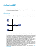
Configuring VRRP The term "interface" in this chapter refers to Layer 3 Ethernet interfaces, and VLAN interfaces. You can configure an Ethernet port as a Layer 3 interface by using the port link-mode route command (see Layer 2—LAN Switching Configuration Guide). Overview Typically, you can configure a default gateway for every host on a LAN. All packets destined for other networks are sent through the default gateway.
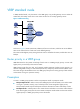
VRRP standard mode In VRRP standard mode, only the master in the VRRP group can provide gateway service. When the master fails, the backup routers elect a new master to take over for nonstop gateway service. Figure 2 VRRP networking As shown in Figure 2, Router A, Router B, and Router C form a virtual router, which has its own IP address. Hosts on the subnet use the virtual router as the default gateway.
Authentication method To avoid attacks from unauthorized users, VRRP member routers add authentication keys in VRRP packets to authenticate one another. VRRP provides the following authentication methods: • Simple authentication The sender fills an authentication key into the VRRP packet, and the receiver compares the received authentication key with its local authentication key. If the two authentication keys match, the received VRRP packet is legitimate.
Master election Routers in a VRRP group determine their roles by priority. When a router joins a VRRP group, it has a backup role. The router role changes according to the following situations: • If the backup does not receive any VRRP advertisement when the timer (3 × advertisement interval + Skew_Time) expires, it becomes the master. • If the backup receives a VRRP advertisement with a greater or the same priority within the timer (3 × advertisement interval + Skew_Time), it remains a backup.
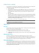
Figure 3 VRRP in master/backup mode Assume that Router A is acting as the master to forward packets to external networks, and Router B and Router C are backups in listening state. When Router A fails, Router B and Router C elect a new master to forward packets for hosts on the subnet. Load sharing A router can join multiple VRRP groups and has different priorities in different VRRP groups, and it can act as the master in one VRRP group and a backup in another.
• VRRP group 1—Router A is the master. Router B and Router C are the backups. • VRRP group 2—Router B is the master. Router A and Router C are the backups. • VRRP group 3—Router C is the master. Router A and Router B are the backups. To implement load sharing among Router A, Router B, and Router C, hosts on the subnet must be configured with the virtual IP addresses of VRRP group 1, 2, and 3 as default gateways, respectively.
Creating a VRRP group and assigning a virtual IP address A VRRP group can operate correctly after you create it and assign at least one virtual IP address to it. You can configure multiple virtual IP addresses for the VRRP group on an interface that connects to multiple subnets for router backup on different subnets.
Configuration procedure To configure the router priority, preemptive mode, and tracking function: Step Command Remarks 1. Enter system view. system-view N/A 2. Enter interface view. interface interface-type interface-number N/A 3. Configure the priority of the router in the VRRP group. vrrp vrid virtual-router-id priority priority-value The default setting is 100. 4. Enable the preemptive mode for the router in a VRRP group and configure the preemption delay time.
Step 4. Command Configure the interval at which the master in an IPv4 VRRP group sends VRRP advertisements. Remarks The default setting is 100 centiseconds. vrrp vrid virtual-router-id timer advertise adver-interval To maintain system stability, HP recommends setting the VRRP advertisement interval to be greater than 100 centiseconds. 5. Specify the source interface for receiving and sending VRRP packets.
Step Command Remarks 2. Enter interface view. interface interface-type interface-number N/A 3. Disable a VRRP group. vrrp vrid virtual-router-id shutdown By default, a VRRP group is enabled. Displaying and maintaining IPv4 VRRP Execute display commands in any view and the reset command in user view. Task Command Display states of IPv4 VRRP groups. display vrrp [ interface interface-type interface-number [ vrid virtual-router-id ] ] [ verbose ] Display statistics for IPv4 VRRP groups.
Figure 5 Network diagram Configuration procedure 1. Configure Switch A: # Configure VLAN 2. system-view [SwitchA] vlan 2 [SwitchA-vlan2] port fortygige 1/0/5 [SwitchA-vlan2] quit [SwitchA] interface vlan-interface 2 [SwitchA-Vlan-interface2] ip address 10.1.1.1 255.255.255.0 # Create VRRP group 1 on VLAN-interface 2, and set its virtual IP address to 10.1.1.111. [SwitchA-Vlan-interface2] vrrp vrid 1 virtual-ip 10.1.1.
[SwitchB-Vlan-interface2] vrrp vrid 1 preempt-mode delay 5 3. Verify the configuration: # Ping Host B from Host A. (Details not shown.) # Display detailed information about VRRP group 1 on Switch A.
Virtual MAC : 0000-5e00-0101 Master IP : 10.1.1.2 The output shows that when Switch A fails, Switch B takes over to forward packets from Host A to Host B. # Recover the link between Host A and Switch A, and display detailed information about VRRP group 1 on Switch A.
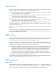
Figure 6 Network diagram Virtual IP address 1: 10.1.1.100/25 XGE1/0/5 Vlan-int2 10.1.1.1/25 XGE1/0/6 Vlan-int3 10.1.1.130/25 VLAN 2 Gateway: 10.1.1.100/25 Switch A Internet VLAN 3 XGE1/0/5 Vlan-int2 10.1.1.2/25 XGE1/0/6 Vlan-int3 10.1.1.131/25 Gateway: 10.1.1.200/25 Switch B Virtual IP address 2: 10.1.1.200/25 Configuration procedure 1. Configure Switch A: # Configure VLAN 2.
[SwitchB-Vlan-interface2] ip address 10.1.1.2 255.255.255.128 # Create VRRP group 1, and set its virtual IP address to 10.1.1.100. [SwitchB-Vlan-interface2] vrrp vrid 1 virtual-ip 10.1.1.100 [SwitchB-Vlan-interface2] quit # Configure VLAN 3. [SwitchB] vlan 3 [SwitchB-vlan3] port fortygige 1/0/6 [SwitchB-vlan3] quit [SwitchB] interface vlan-interface 3 [SwitchB-Vlan-interface3] ip address 10.1.1.131 255.255.255.128 # Create VRRP group 2, and set its virtual IP address to 10.1.1.200.
Admin Status : Up State : Backup Config Pri : 100 Running Pri : 100 Preempt Mode : Yes Delay Time : 0 Become Master : 211ms left Auth Type : None Virtual IP : 10.1.1.100 Master IP : 10.1.1.1 Interface Vlan-interface3 VRID : 2 Adver Timer : 100 Admin Status : Up State : Master Config Pri : 110 Running Pri : 110 Preempt Mode : Yes Delay Time : 0 Auth Type : None Virtual IP : 10.1.1.200 Virtual MAC : 0000-5e00-0102 Master IP : 10.1.1.
Multiple masters appear in a VRRP group Symptom Multiple masters appear in a VRRP group. Analysis It is normal for a VRRP group to have multiple masters for a short time, and this situation requires no manual intervention. If multiple masters coexist for a longer period, it might be because the masters cannot receive advertisements from each other, or because the received advertisements are illegitimate.
Configuring BFD The term "interface" in this chapter collectively refers to Layer 3 interfaces, including VLAN interfaces and Layer 3 Ethernet interfaces. You can set an Ethernet port as a Layer 3 interface by using the port link-mode route command (see Layer 2—LAN Switching Configuration Guide). Overview Bidirectional forwarding detection (BFD) provides a general-purpose, standard, medium- and protocol-independent fast failure detection mechanism.
BFD session modes and operating modes BFD sessions use the following types of packets: • Echo packets—Encapsulated into UDP packets with port number 3785. • Control packets—Encapsulated into UDP packets with port number 3784 for single-hop detection or port number 4784 for multi-hop detection. Echo packet mode The local end of the link sends echo packets to establish BFD sessions and monitor link status.
Protocols and standards • RFC 5880, Bidirectional Forwarding Detection (BFD) • RFC 5881, Bidirectional Forwarding Detection (BFD) for IPv4 and IPv6 (Single Hop) • RFC 5882, Generic Application of Bidirectional Forwarding Detection (BFD) • RFC 5883, Bidirectional Forwarding Detection (BFD) for Multihop Paths • RFC 5885, Bidirectional Forwarding Detection (BFD) for the Pseudowire Virtual Circuit Connectivity Verification (VCCV) Configuring BFD basic functions Before configuring BFD basic functions,
Step Command Remarks 1. Enter system view. system-view N/A 2. Specify the mode for establishing a BFD session. bfd session init-mode { active | passive } By default, active is specified. 3. Enter interface view. interface interface-type interface-number N/A 4. Configure the authentication mode for single-hop control packets. bfd authentication-mode simple key-id { cipher cipher-string | plain plain-string } By default, single-hop BFD packets are not authenticated. 5.
Step 7. Configure the minimum interval for transmitting multi-hop BFD control packets. Command Remarks bfd multi-hop min-transmit-interval value The default setting is 400 milliseconds. Displaying and maintaining BFD Execute the display command in any view and the reset command in user view. Task Command Display BFD session information. display bfd session [ discriminator value | verbose ] Clear BFD session statistics.
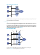
Configuring Track Overview The Track module works between application modules and detection modules, as shown in Figure 7. It shields the differences between various detection modules from application modules. Collaboration is enabled after you associate the Track module with a detection module and an application module. The detection module probes specific objects such as interface status, link status, network reachability, and network performance, and informs the Track module of detection results.
• BFD. • Interface management. Collaboration between the Track module and an application module The following application modules can be associated with the Track module: • VRRP. • Static routing. • Policy-based routing. When configuring a track entry for an application module, you can set a notification delay to avoid immediate notification of status changes, which can cause communication failure. This issue occurs when route convergence is slower than the link state change notification.
Tasks at a glance Remarks (Required.) Associating the Track module with an application module: • Associating Track with VRRP • Associating Track with static routing • Associating Track with PBR Use one of the methods. Associating the Track module with a detection module Associating Track with NQA NQA supports multiple test types to analyze network performance, services, and service quality.
If the BFD detects that the link is operating correctly, the Track module sets the track entry to Positive state. • Configuration prerequisites Before you associate Track with BFD, configure the source IP address of BFD echo packets. For more information, see "Configuring BFD." Configuration procedure To associate Track with BFD: Step 1. Enter system view. 2.
Step Command Remarks • Create a track entry, associate it with 2. Associating Track with interface management.
You can associate a nonexistent track entry with a VRRP group. The association takes effect only after you use the track command to create the track entry. • To associate Track with VRRP group: Step Command Remarks 1. Enter system view. system-view N/A 2. Enter interface view. interface interface-type interface-number N/A 3. Associate a track entry with a VRRP group.
Step Associate the static route with a track entry to check the accessibility of the next hop. 2. Command Remarks ip route-static dest-address { mask | mask-length } { next-hop-address [ track track-entry-number ] | interface-type interface-number [ next-hop-address ] } [ permanent ] [ preference preference-value ] [ tag tag-value ] [ description description-text ] Not configured by default. Associating Track with PBR PBR is a routing mechanism based on user-defined policies.
Step Command Remarks Create a policy or policy node and enter PBR policy node view. policy-based-route policy-name [ deny | permit ] node node-number N/A 3. Define a match criterion. if-match acl { acl-number | name acl-name } By default, no packets are filtered. 4. Associate Track with PBR. apply next-hop { ip-address [ direct ] [ track track-entry-number ] }&<1-n> N/A 2. Displaying and maintaining track entries Execute the display command in any view.
Figure 8 Network diagram Configuration procedure 1. Create VLANs and assign corresponding ports to them. Configure the IP address of each VLAN interface as shown in Figure 8. (Details not shown.) 2. Configure an NQA test group on Switch A: # Create an NQA test group with the administrator name admin and the operation tag test. system-view [SwitchA] nqa entry admin test # Configure the test type as ICMP-echo. [SwitchA-nqa-admin-test] type icmp-echo # Configure the destination address as 10.1.
[SwitchA-Vlan-interface2] vrrp vrid 1 authentication-mode simple hello # Configure the master to send VRRP packets at an interval of 500 centiseconds. [SwitchA-Vlan-interface2] vrrp vrid 1 timer advertise 500 # Configure Switch A to operate in preemptive mode, and set the preemption delay to 5 seconds. [SwitchA-Vlan-interface2] vrrp vrid 1 preempt-mode timer delay 5 # Configure to monitor track entry 1, and specify the priority decrement to 30. [SwitchA-Vlan-interface2] vrrp vrid 1 track 1 reduced 30 5.
Config Pri : 100 Running Pri : 100 Preempt Mode : Yes Delay Time : 5 Become Master : 2200ms left Auth Type : Simple Key : ****** Virtual IP : 10.1.1.10 Master IP : 10.1.1.1 The output shows that in VRRP group 1, Switch A is the master, and Switch B is a backup. Packets from Host A to Host B are forwarded through Switch A. When a fault is on the link between Switch A and Switch C, you can still successfully ping Host B on Host A.
Configuring BFD for a VRRP backup to monitor the master Network requirements As shown in Figure 9, Switch A and Switch B belong to VRRP group 1, whose virtual IP address is 192.168.0.10. The default gateway of the hosts in the LAN is 192.168.0.10. When Switch A works correctly, the hosts in the LAN access the external network through Switch A. When Switch A fails, the hosts in the LAN access the external network through Switch B.
3. On Switch B, configure the source address of BFD echo packets as 10.10.10.10. system-view [SwitchB] bfd echo-source-ip 10.10.10.10 4. On Switch B, create track entry 1 to be associated with the BFD session to check whether Switch A is reachable. [SwitchB] track 1 bfd echo interface vlan-interface 2 remote ip 192.168.0.101 local ip 192.168.0.102 5. On Switch B, create VRRP group 1, and configure the virtual IP address 192.168.0.10 for the group.
Track ID: 1 State: Positive Duration: 0 days 0 hours 0 minutes 32 seconds Notification delay: Positive 0, Negative 0 (in seconds) Tracked object: BFD session mode: Echo Outgoing interface: Vlan-interface2 VPN instance name: Remote IP: 192.168.0.101 Local IP: 192.168.0.102 The output shows that when the status of the track entry becomes Positive, Switch A is the master and Switch B the backup. # Enable VRRP state debugging and BFD event debugging on Switch B.
Configuring BFD for the VRRP master to monitor the uplinks Network requirements As shown in Figure 10, Switch A and Switch B belong to VRRP group 1, whose virtual IP address is 192.168.0.10. The default gateway of the hosts in the LAN is 192.168.0.10. When Switch A works correctly, the hosts in the LAN access the external network through Switch A.
1 to monitor the status of track entry 1. When the status of the track entry becomes Negative, the priority of Switch A decreases by 20. [SwitchA] interface vlan-interface 2 [SwitchA-Vlan-interface2] vrrp vrid 1 virtual-ip 192.168.0.10 [SwitchA-Vlan-interface2] vrrp vrid 1 priority 110 [SwitchA-Vlan-interface2] vrrp vrid 1 track 1 reduced 20 [SwitchA-Vlan-interface2] return 5. On Switch B, create VRRP group 1, and configure the virtual IP address of the group as 192.168.0.10.
Interface Vlan-interface2 VRID : 1 Adver Timer : 100 Admin Status : Up State : Backup Config Pri : 100 Running Pri : 100 Preempt Mode : Yes Delay Time : 0 Become Master : 2200ms left Auth Type : None Virtual IP : 192.168.0.10 Master IP : 192.168.0.101 The output shows that when the status of track entry 1 becomes Positive, Switch A is the master, and Switch B the backup. # When the uplink of Switch A goes down, the status of track entry 1 becomes Negative.
Config Pri : 100 Running Pri : 100 Preempt Mode : Yes Delay Time : 0 Auth Type : None Virtual IP : 192.168.0.10 Virtual MAC : 0000-5e00-0101 Master IP : 192.168.0.102 The output shows that when Switch A detects that the uplink fails through BFD, it decreases its priority by 20 to make sure that Switch B can preempt as the master.
Figure 11 Network diagram Configuration procedure 1. Create VLANs and assign corresponding ports to them. Configure the IP address of each VLAN interface as shown in Figure 11. (Details not shown.) 2. Configure Switch A: # Configure a static route to 30.1.1.0/24, with the address of the next hop as 10.2.1.2 and the default priority 60. This static route is associated with track entry 1. system-view [SwitchA] ip route-static 30.1.1.0 24 10.2.1.2 track 1 # Configure a static route to 30.1.1.
[SwitchC] ip route-static 30.1.1.0 24 10.4.1.2 # Configure a static route to 20.1.1.0/24, with the address of the next hop as 10.3.1.1. [SwitchB] ip route-static 20.1.1.0 24 10.3.1.1 Verifying the configuration # Display information about the track entry on Switch A.
Remote IP: 10.2.1.2 Local IP: 10.2.1.1 # Display the routing table of Switch A. [SwitchA] display ip routing-table Routing Tables: Public Destinations : 9 Routes : 9 Destination/Mask Proto Cost NextHop Interface 10.2.1.0/24 Direct 0 Pre 0 10.2.1.1 Vlan2 10.2.1.1/32 Direct 0 0 127.0.0.1 InLoop0 10.3.1.0/24 Direct 0 0 10.3.1.1 Vlan3 10.3.1.1/32 Direct 0 0 127.0.0.1 InLoop0 20.1.1.0/24 Direct 0 0 20.1.1.1 Vlan5 20.1.1.1/32 Direct 0 0 127.0.0.1 InLoop0 30.1.1.
VRRP-Track-interface management collaboration configuration example In this example, the master monitors the uplink interface. Network requirements As shown in Figure 12, Host A needs to access Host B on the Internet. The default gateway of Host A is 10.1.1.10/24. Switch A and Switch B belong to VRRP group 1, whose virtual IP address is 10.1.1.10. When Switch A works correctly, packets from Host A to Host B are forwarded through Switch A.
[SwitchB] interface vlan-interface 2 # Create VRRP group 1 and configure the virtual IP address 10.1.1.10 for the group. [SwitchB-Vlan-interface2] vrrp vrid 1 virtual-ip 10.1.1.10 Verifying the configuration After configuration, ping Host B on Host A, and you can see that Host B is reachable. Use the display vrrp command to view the configuration result. # Display detailed information about VRRP group 1 on Switch A.
[SwitchA-Vlan-interface3] display vrrp verbose IPv4 Virtual Router Information: Running Mode : Standard Total number of virtual routers : 1 Interface Vlan-interface2 VRID : 1 Adver Timer : 100 Admin Status : Up State : Backup Config Pri : 110 Running Pri : 80 Preempt Mode : Yes Delay Time : 0 Become Master : 2200ms left Auth Type : None Virtual IP : 10.1.1.10 Master IP : 10.1.1.
Support and other resources Contacting HP For worldwide technical support information, see the HP support website: http://www.hp.
Conventions This section describes the conventions used in this documentation set. Command conventions Convention Description Boldface Bold text represents commands and keywords that you enter literally as shown. Italic Italic text represents arguments that you replace with actual values. [] Square brackets enclose syntax choices (keywords or arguments) that are optional. { x | y | ... } Braces enclose a set of required syntax choices separated by vertical bars, from which you select one.
Network topology icons Represents a generic network device, such as a router, switch, or firewall. Represents a routing-capable device, such as a router or Layer 3 switch. Represents a generic switch, such as a Layer 2 or Layer 3 switch, or a router that supports Layer 2 forwarding and other Layer 2 features. Represents an access controller, a unified wired-WLAN module, or the switching engine on a unified wired-WLAN switch. Represents an access point.
Index A protocols and standards, 20 advertising session establishment, 18 session modes, 19 high availability VRRP advertisement interval, 3 single-hop detection, 18 application static routing-Track-BFD collaboration, 40 high availability VRRP, 4 supported features, 19 high availability VRRP load-sharing, 5 Track BFD/VRRP backup master monitor, 34 high availability VRRP master/backup, 4 Track BFD/VRRP master uplink monitor, 37 Track application collaboration, 24 Track/application module associ
static routing-Track-BFD collaboration, 40 displaying Track, 23, 24, 30 high availability BFD, 22 Track BFD/VRRP backup master monitor, 34 high availability IPv4 VRRP, 10 Track BFD/VRRP master uplink monitor, 37 track entries, 30 VRRP-Track-interface management collaboration, 44 VRRP-Track-NQA collaboration, 30 controlling high availability BFD control packet mode, 20 creating high availability IPv4 VRRP group, 7 D detecting high availability BFD configuration, 18 Track application collaboration, 24
static routing-Track-BFD collaboration, 40 router tracking function configuration, 7 Track application collaboration, 24 single group configuration, 10 Track BFD/VRRP backup master monitor, 34 SNMP notification enable, 9 Track BFD/VRRP master uplink monitor, 37 version specification, 6 Track configuration, 23, 24, 30 virtual IP address assignment, 7 troubleshooting VRRP, 16 IPv6 troubleshooting VRRP error prompt displayed, 16 high availability BFD protocols and standards, 20 troubleshooting VR
high availability VRRP master/backup application, 4 VRRP-Track-interface management collaboration, 44 high availability VRRP multiple masters appear in group, 17 VRRP-Track-NQA collaboration, 30 MD5 authentication multi-hop high availability BFD control packet mode, 20 high availability VRRP, 3 mode high availability BFD control packet active operating mode, 19 high availability BFD control packet asynchronous operating mode, 19 high availability BFD mode, 18 multi-hop detection (BFD), 20 N network h
static routing-Track-BFD collaboration, 40 associating Track/NQA, 25 Track BFD/VRRP backup master monitor, 34 associating Track/policy-based routing, 29 Track BFD/VRRP master uplink monitor, 37 associating Track/static routing, 28 Track configuration, 23, 24, 30 associating Track/VRRP, 27 VRRP-Track-interface management collaboration, 44 configuring high availability BFD basic functions, 20 VRRP-Track-NQA collaboration, 30 configuring high availability BFD control packet mode (multi-hop detection
troubleshooting high availability VRRP multiple masters appear in group, 17 troubleshooting VRRP fast state flapping, 17 protocols and standards high availability BFD, 20 high availability BFD control packet mode, 20 high availability BFD mode, 18 single-hop detection (BFD), 20 Skew-Time (VRRP), 3 specifying high availability VRRP, 6 high availability IPv4 VRRP version, 6 standard operating mode (VRRP), 1, 2 R static RIP high availability BFD-supported, 19 router high availability BFD supported stati
high availability BFD supported, 19 operating mode (load-balancing), 1 high availability IPv4 VRRP router tracking, 7 operating mode (standard), 1, 2 interface management association, 26 protocols and standards, 6 NQA association, 25 router preemption, 2 policy-based routing association, 29 timers, 3 static routing association, 28 Track BFD/VRRP backup master monitor, 34 static routing-Track-BFD collaboration configuration, 40 Track BFD/VRRP master uplink monitor, 37 Track/application module co