HP FlexFabric 7900 Switch Series IP Multicast Configuration Guide Part number: 5998-4284 Software version: Release 2109 Document version: 6W100-20140122
Legal and notice information © Copyright 2014 Hewlett-Packard Development Company, L.P. No part of this documentation may be reproduced or transmitted in any form or by any means without prior written consent of Hewlett-Packard Development Company, L.P. The information contained herein is subject to change without notice.
Contents Multicast overview ······················································································································································· 1 Introduction to multicast ···················································································································································· 1 Information transmission techniques ·····················································································································
Configuring the RPF route selection rule ············································································································· 39 Configuring multicast load splitting ····················································································································· 39 Configuring a multicast forwarding boundary ··································································································· 40 Configuring static multicast MAC address entries ····
Configuring switchover to SPT ····························································································································· 78 Configuring PIM-SSM ···················································································································································· 78 PIM-SSM configuration task list ···························································································································· 79 Configuration prerequ
Multicast overview Introduction to multicast As a technique that coexists with unicast and broadcast, the multicast technique effectively addresses the issue of point-to-multipoint data transmission. By enabling high-efficiency point-to-multipoint data transmission over a network, multicast greatly saves network bandwidth and reduces network load.
a separate copy of the same information to each of these hosts. Sending many copies can place a tremendous pressure on the information source and the network bandwidth. Unicast is not suitable for batch transmission of information. Broadcast In broadcast transmission, the information source sends information to all hosts on the subnet, even if some hosts do not need the information. Figure 2 Broadcast transmission In Figure 2, assume that only Host B, Host D, and Host E need the information.
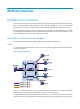
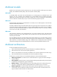
Figure 3 Multicast transmission The multicast source sends only one copy of the information to a multicast group. Host B, Host D, and Host E, which are information receivers, must join the multicast group. The routers on the network duplicate and forward the information based on the distribution of the group members. Finally, the information is correctly delivered to Host B, Host D, and Host E.
For a better understanding of the multicast concept, you can compare multicast transmission to the transmission of TV programs. Table 1 Comparing TV program transmission and multicast transmission TV program transmission Multicast transmission A TV station transmits a TV program through a channel. A multicast source sends multicast data to a multicast group. A user tunes the TV set to the channel. A receiver joins the multicast group.
Multicast models Based on how the receivers treat the multicast sources, the multicast models include any-source multicast (ASM), source-filtered multicast (SFM), and source-specific multicast (SSM). ASM model In the ASM model, any sender can send information to a multicast group as a multicast source, and receivers can join a multicast group identified by a group address and get multicast information addressed to that multicast group.
Multicast addresses IP multicast addresses • IPv4 multicast addresses: IANA assigns the Class D address block (224.0.0.0 to 239.255.255.255) to IPv4 multicast. Table 2 Class D IP address blocks and description Address block Description 224.0.0.0 to 224.0.0.255 Reserved permanent group addresses. The IP address 224.0.0.0 is reserved. Other IP addresses can be used by routing protocols and for topology searching, protocol maintenance, and so on. Table 3 lists common permanent group addresses.
Address Description 224.0.0.13 All Protocol Independent Multicast (PIM) routers. 224.0.0.14 RSVP encapsulation. 224.0.0.15 All Core-Based Tree (CBT) routers. 224.0.0.16 Designated SBM. 224.0.0.17 All SBMs. 224.0.0.18 VRRP. IPv6 multicast addresses: • Figure 4 IPv6 multicast format 0 7 0xFF 11 Flags 15 31 Scope Group ID (112 bits) The following describes the fields of an IPv6 multicast address: { 0xFF—The most significant eight bits are 11111111.
Table 5 Values of the Scope field Value Meaning 0, F Reserved. 1 Interface-local scope. 2 Link-local scope. 3 Subnet-local scope. 4 Admin-local scope. 5 Site-local scope. 6, 7, 9 through D Unassigned. 8 Organization-local scope. E Global scope. { Group ID—The Group ID field contains 112 bits. It uniquely identifies an IPv6 multicast group in the scope that the Scope field defines.
Figure 7 IPv6-to-MAC address mapping Multicast protocols Multicast protocols include the following categories: • Layer 3 and Layer 2 multicast protocols: { Layer 3 multicast refers to IP multicast working at the network layer. Layer 3 multicast protocols—IGMP, MLD, PIM, IPv6 PIM, MSDP, MBGP, and IPv6 MBGP. { Layer 2 multicast refers to IP multicast working at the data link layer.
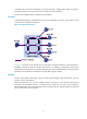
Figure 8 Positions of Layer 3 multicast protocols Receiver AS 1 Receiver IGMP/MLD IGMP/MLD PIM/IPv6 PIM AS 2 PIM/IPv6 PIM MBGP/MSDP IPv6 MBGP IGMP/MLD Receiver Source • Multicast group management protocols: Typically, the Internet Group Management Protocol (IGMP) or Multicast Listener Discovery (MLD) protocol is used between hosts and Layer 3 multicast devices that directly connect to the hosts to define how to establish and maintain their multicast group memberships.
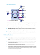
Figure 9 Positions of Layer 2 multicast protocols Source 1 Multicast VLAN /IPv6 Multicast VLAN IGMP Snooping /MLD Snooping PIM Snooping /IPv6 PIM Snooping Receiver Receiver Source 2 Receiver IPv4/IPv6 multicast packets (S1, G1) • IPv4/IPv6 multicast packets (S2, G2) IGMP snooping and MLD snooping: IGMP snooping and MLD snooping run on Layer 2 devices as multicast constraining mechanisms to improve multicast forwarding efficiency.
incoming interface. The RPF check result determines whether the packet will be forwarded or discarded. The RPF check mechanism is the basis for most multicast routing protocols to implement multicast forwarding. For more information about the RPF mechanism, see "Configuring multicast routing and forwarding.
Configuring IGMP snooping Overview IGMP snooping runs on a Layer 2 switch as a multicast constraining mechanism to improve multicast forwarding efficiency. It creates Layer 2 multicast forwarding entries from IGMP packets that are exchanged between the hosts and the router. As shown in Figure 10, when IGMP snooping is not enabled, the Layer 2 switch floods multicast packets to all hosts.
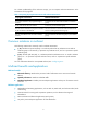
Figure 11 IGMP snooping related ports Router A Receiver Switch A FGE1/0/1 FGE1/0/2 Host A FGE1/0/3 Host B Receiver FGE1/0/1 Source FGE1/0/2 Switch B Host C Router port Member port Multicast packets Host D The following describes the ports involved in IGMP snooping: • Router port—Layer 3 multicast device-side port. Layer 3 multicast devices include designated routers (DRs) and IGMP queriers. In Figure 11, FortyGigE 1/0/1 of Switch A and FortyGigE 1/0/1 of Switch B are the router ports.
NOTE: In IGMP snooping, only dynamic ports age out. Static ports never age out. How IGMP snooping works The ports in this section are dynamic ports. For information about how to configure and remove static ports, see "Configuring static ports." IGMP messages types include general query, IGMP report, and leave message. An IGMP snooping-enabled switch performs differently depending on the message.
determine whether the reported multicast group still has active members attached to that port. For more information about the IGMP report suppression mechanism, see "Configuring IGMP." Leave message An IGMPv1 host silently leaves a multicast group, and the switch is not notified of the leave.
Task at a glance • (Optional.) Setting the maximum number of IGMP snooping forwarding entries • (Optional.) Configuring parameters for IGMP queries and responses Configuring IGMP snooping port functions: • (Optional.) Setting aging timers for dynamic ports • (Optional.) Configuring static ports • (Optional.) Enabling IGMP snooping fast-leave processing Configuring IGMP snooping policies: • • • • • • (Optional.) Configuring a multicast group filter (Optional.
Step Enable IGMP snooping for specified VLANs. 3. Command Remarks enable vlan vlan-list By default, IGMP snooping is disabled for a VLAN. To enable IGMP snooping for a VLAN in VLAN view: Step Command Remarks 1. Enter system view. system-view N/A 2. Enable IGMP snooping globally and enter IGMP-snooping view. igmp-snooping By default, IGMP snooping is disabled. 3. Return to system view. quit N/A 4. Enter VLAN view. vlan vlan-id N/A 5. Enable IGMP snooping for the VLAN.
Step Command Remarks 1. Enter system view. system-view N/A 2. Enter VLAN view. vlan vlan-id N/A 3. Specify the version of IGMP snooping. igmp-snooping version version-number The default setting is IGMPv2 snooping. Setting the maximum number of IGMP snooping forwarding entries You can modify the maximum number of IGMP snooping forwarding entries.
Step 3. 4. Command Remarks Set the maximum response time for IGMP general queries. max-response-time interval The default setting is 10 seconds. Set the IGMP last-member query interval. last-member-query-interval interval The default setting is 1 second. Configuring parameters for IGMP queries and responses in a VLAN Step Command Remarks 1. Enter system view. system-view N/A 2. Enter VLAN view. vlan vlan-id N/A 3. Set the maximum response time for IGMP general queries in the VLAN.
Step Command Remarks 3. Set the aging timer for dynamic router ports globally. router-aging-time interval The default setting is 260 seconds. 4. Set the global aging timer for dynamic member ports globally. host-aging-time interval The default setting is 260 seconds. Setting the aging timers for the dynamic ports in a VLAN Step Command Remarks 1. Enter system view. system-view N/A 2. Enter VLAN view. vlan vlan-id N/A 3. Set the aging timer for the dynamic router ports in the VLAN.
Enabling IGMP snooping fast-leave processing The IGMP snooping fast-leave processing feature enables the switch to process IGMP leave messages quickly. When a port that is enabled with the IGMP snooping fast-leave processing feature receives an IGMP leave message, the switch immediately removes that port from the forwarding entry for the multicast group specified in the message. Then, when the switch receives IGMP group-specific queries for that multicast group, it does not forward them to that port.
• This configuration is effective on the multicast groups that a port dynamically joins. If you configure the port as a static member port for a multicast group, this configuration is not effective on the multicast group. • You can configure a multicast filter either for the current port in interface view or globally for all ports in IGMP-snooping view. If the configurations are made in both interface view and IGMP-snooping view, the configuration made in interface view takes priority.
Configuring multicast source port filtering on a port Step Command Remarks 1. Enter system view. system-view N/A 2. Enter Layer 2 Ethernet interface view. interface interface-type interface-number N/A 3. Enable multicast source port filtering. igmp-snooping source-deny By default, the multicast source port filtering is disabled. Enabling dropping unknown multicast data Unknown multicast data refers to multicast data for which no forwarding entries exist in the IGMP snooping forwarding table.
Setting the maximum number of multicast groups on a port You can set the maximum number of multicast groups on a port to regulate the port traffic. When you set the maximum number of multicast groups on a port, follow these guidelines: • This configuration is effective on the multicast groups that a port dynamically joins. If you configure the port as a static member port for a multicast group, this configuration is not effective for the multicast group.
Step Command Remarks 2. Enter IGMP-snooping view. igmp-snooping N/A 3. Enable the multicast group replacement function globally. overflow-replace [ vlan vlan-list ] By default, the multicast group replacement function is disabled. To enable the multicast group replacement function on a port: Step Command Remarks 1. Enter system view. system-view N/A 2. Enter Layer 2 Ethernet interface view or Layer 2 aggregate interface view.
Task Command Display information about Layer 2 IP multicast groups (in standalone mode). display l2-multicast ip [ group group-address | source source-address ] * [ vlan vlan-id ] [ slot slot-number ] Display information about Layer 2 IP multicast groups (in IRF mode). display l2-multicast ip [ group group-address | source source-address ] * [ vlan vlan-id ] [ chassis chassis-number slot slot-number ] Display information about Layer 2 IP multicast group entries (in standalone mode).
Figure 12 Network diagram Receiver Host A Source FGE1/0/2 1.1.1.2/24 1.1.1.1/24 FGE1/0/1 10.1.1.1/24 FGE1/0/4 FGE1/0/1 Router A IGMP querier Receiver FGE1/0/3 Switch A FGE1/0/2 Host B Host C VLAN 100 Configuration procedure 1. Assign an IP address and subnet mask to each interface according to Figure 12. (Details not shown.) 2. On Router A: # Enable IP multicast routing. system-view [RouterA] multicast routing [RouterA-mrib] quit # Enable IGMP and PIM-DM on FortyGigE 1/0/1.
[SwitchA-vlan100] quit # Configure a multicast group filter so that the hosts in VLAN 100 can join only the multicast group 224.1.1.1. [SwitchA] acl number 2001 [SwitchA-acl-basic-2001] rule permit source 224.1.1.1 0 [SwitchA-acl-basic-2001] quit [SwitchA] igmp-snooping [SwitchA-igmp-snooping] group-policy 2001 vlan 100 [SwitchA-igmp-snooping] quit Verifying the configuration # Send IGMP reports from Host A and Host B to join the multicast groups 224.1.1.1 and 224.2.2.2. (Details not shown.
NOTE: If no static router port is configured, when the path of Switch A—Switch B—Switch C is blocked, at least one IGMP query-response cycle must be completed before the multicast data can flow to the receivers along the new path of Switch A—Switch C, so multicast delivery is interrupted during this process. For more information about the STP, see Layer 2—LAN Switching Configuration Guide. Figure 13 Network diagram Configuration procedure 1.
system-view [SwitchA] igmp-snooping [SwitchA-igmp-snooping] quit # Create VLAN 100, assign FortyGigE 1/0/1 through FortyGigE 1/0/3 to the VLAN, and enable IGMP snooping for the VLAN. [SwitchA] vlan 100 [SwitchA-vlan100] port fortygige 1/0/1 to fortygige 1/0/3 [SwitchA-vlan100] igmp-snooping enable [SwitchA-vlan100] quit # Configure FortyGigE 1/0/3 as a static router port.
VLAN 100: Router slots (1 in total): 1 Router ports (1 in total): 1 FGE1/0/3 The output shows that FortyGigE 1/0/3 on Switch A has become a static router port. # Display information about the static IGMP snooping forwarding entries in VLAN 100 on Switch C. [SwitchC] display igmp-snooping static-group vlan 100 Total 1 entries. VLAN 100: Total 1 entries. (0.0.0.0, 224.1.1.
Analysis • The ACL is incorrectly configured. • The multicast group filter is not correctly applied. • The function of dropping unknown multicast data is not enabled, so unknown multicast data is flooded. 1. Use the display acl command to verify that the configured ACL meets the multicast group filter requirements. 2. Use the display this command in IGMP-snooping view or in a corresponding interface view to verify that the correct multicast group filter has been applied.
Configuring multicast routing and forwarding Overview The following tables are involved in multicast routing and forwarding: • Multicast routing table of each multicast routing protocol, such as the PIM routing table. • General multicast routing table that summarizes multicast routing information generated by different multicast routing protocols. The multicast routing information from multicast sources to multicast groups are stored in a set of (S, G) routing entries.
priority as the RPF route. If the routes have the same priority, the router selects a route as the RPF route in the order of static multicast route and unicast route. For more information about the route priority, see Layer 3—IP Routing Configuration Guide. { If the router does not use the longest prefix match principle, the router selects the route that has the highest priority as the RPF route.
Figure 14 RPF check process IP Routing Table on Switch C Destination/Mask Interface 192.168.0.0/24 Vlan-int20 Switch B Receiver Vlan-int10 Source 192.168.0.1/24 Switch A Vlan-int10 Receiver Vlan-int20 Multicast packets Switch C As shown in Figure 14, assume that unicast routes are available on the network, and no static multicast routes have been configured on Switch C. A multicast packet (S, G) travels along the SPT from the multicast source to the receivers.
Figure 15 Changing an RPF route Multicast Routing Table Static on Switch C Source/Mask Interface RPF neighbor/Mask 192.168.0.0/24 Vlan-int10 1.1.1.1/24 Switch B Receiver Multicast packets Multicast static route Vlan-int10 1.1.1.1/24 Source Vlan-int10 1.1.1.2/24 Receiver Vlan-int20 192.168.0.
and Switch D, specifying Switch B as the RPF neighbor of Switch C and Switch C as the RPF neighbor of Switch D, the receiver hosts can receive the multicast data from the multicast source. NOTE: A static multicast route is effective only on the multicast router on which it is configured, and will not be advertised throughout the network or redistributed to other routers. Configuration task list Tasks at a glance (Required.) Enabling IP multicast routing (Optional.
Configuring static multicast routes By configuring a static multicast route for a given multicast source, you can specify an RPF interface or an RPF neighbor for the multicast traffic from that source. To configure a static multicast route: Step Command Remarks 1. Enter system view. system-view N/A 2. Configure a static multicast route.
Configuring a multicast forwarding boundary A multicast forwarding boundary sets the boundary condition for the multicast groups in a specific range. The multicast data for a multicast group travels within a definite boundary in a network. If the destination address of a multicast packet matches the boundary condition, the packet is not forwarded.
Step Command Remarks 1. Enter system view. system-view N/A 2. Enter Ethernet interface/Layer 2 aggregate interface view. interface interface-type interface-number N/A 3. Configure a static multicast MAC address entry. mac-address multicast mac-address vlan vlan-id By default, no static multicast MAC address entries exist. Displaying and maintaining multicast routing and forwarding CAUTION: The reset commands might cause multicast data transmission failures.
Task Command Display information about the static multicast routing table. display multicast routing-table static [ source-address { mask-length | mask } ] Display RPF route information about the multicast source. display multicast rpf-info source-address [ group-address ] Clear statistics for multicast forwarding events. reset multicast forwarding event Clear forwarding entries from the multicast forwarding table.
Figure 17 Network diagram Configuration procedure 1. Assign an IP address and subnet mask for each interface according to Figure 17. (Details not shown.) 2. Configure OSPF on the switches in the PIM-DM domain. (Details not shown.) 3. Enable IP multicast routing, and enable IGMP and PIM-DM: # On Switch B, enable IP multicast routing. system-view [SwitchB] multicast routing [SwitchB-mrib] quit # Enable IGMP on VLAN-interface 100 (the interface that connects to the receiver host).
[SwitchA-Vlan-interface200] quit [SwitchA] interface vlan-interface 102 [SwitchA-Vlan-interface102] pim dm [SwitchA-Vlan-interface102] quit [SwitchA] interface vlan-interface 103 [SwitchA-Vlan-interface103] pim dm [SwitchA-Vlan-interface103] quit # Enable IP multicast routing and PIM-DM on Switch C in the same way Switch A is configured. (Details not shown.) 4. Display the RPF route to the source on Switch B. [SwitchB] display multicast rpf-info 50.1.1.100 RPF information about source 50.1.1.
Figure 18 Network diagram Configuration procedure 1. Assign an IP address and subnet mask for each interface according to Figure 18. (Details not shown.) 2. Enable OSPF on Switch B and Switch C. (Details not shown.) 3. Enable IP multicast routing, and enable IGMP and PIM-DM: # On Switch C, enable IP multicast routing. system-view [SwitchC] multicast routing [SwitchC-mrib] quit # Enable IGMP on VLAN-interface 100 (the interface that connects to the receiver host).
4. Display information about their RPF routes to Source 2 on Switch B and Switch C. [SwitchB] display multicast rpf-info 50.1.1.100 [SwitchC] display multicast rpf-info 50.1.1.100 No output is displayed, because no RPF routes to Source 2 exist on Switch B or Switch C. 5. Configure static multicast routes: # Configure a static multicast route on Switch B, specifying Switch A as its RPF neighbor on the route to Source 2. [SwitchB] ip rpf-route-static 50.1.1.100 24 30.1.1.
Solution 1. Use the display multicast routing-table static command to display information about static multicast routes to verify that the static multicast route has been correctly configured and the route entry exists in the static multicast routing table. 2. Check the type of the interface that connects the static multicast route to the RPF neighbor. If the interface is not a point-to-point interface, be sure to specify the address for the RPF neighbor.
Configuring IGMP Overview Internet Group Management Protocol (IGMP) establishes and maintains the multicast group memberships between a Layer 3 multicast device and its directly connected hosts. IGMP has three versions: • IGMPv1 (defined by RFC 1112) • IGMPv2 (defined by RFC 2236) • IGMPv3 (defined by RFC 3376) All IGMP versions support the ASM model. In addition to the ASM model, IGMPv3 can directly implement the SSM model.
Figure 19 IGMP queries and reports As shown in Figure 19, Host B and Host C are interested in the multicast data addressed to the multicast group G1, and Host A is interested in the multicast data addressed to G2. The following process describes how the hosts join the multicast groups and how the IGMP querier (Router B in Figure 19) maintains the multicast group memberships: 1.
IGMPv2 enhancements Backwards-compatible with IGMPv1, IGMPv2 has introduced a querier election mechanism and a leave-group mechanism. Querier election mechanism In IGMPv1, the DR elected by the Layer 3 multicast routing protocol (such as PIM) serves as the querier among multiple routers that run IGMP on the same subnet. IGMPv2 introduced an independent querier election mechanism. The querier election process is as follows: 1.
• If the host expects to receive multicast data from specific sources like S1, S2, …, it sends a report with the Filter-Mode denoted as "Include Sources (S1, S2, …)." • If the host expects to reject multicast data from specific sources like S1, S2, …, it sends a report with the Filter-Mode denoted as "Exclude Sources (S1, S2, …)". As shown in Figure 20, the network has two multicast sources, Source 1 (S1) and Source 2 (S2). Both of them can send multicast data to the multicast group G.
{ TO_IN—The filtering mode has changed from Exclude to Include. { TO_EX—The filtering mode has changed from Include to Exclude. { { ALLOW—The Source Address fields in this group record contain a list of the additional sources from which the system wants to obtain data for packets sent to the specified multicast address. If the change was to an Include source list, these sources are the addresses that were added to the list.
Enabling IGMP To configure IGMP, enable IGMP on the interface where the multicast group memberships are established and maintained. To enable IGMP: Step Command Remarks 1. Enter system view. system-view N/A 2. Enable IP multicast routing and enter MRIB view. multicast routing By default, IP multicast is disabled. 3. Return to system view. quit N/A 4. Enter interface view. interface interface-type interface-number N/A 5. Enable IGMP. igmp enable By default, IGMP is disabled.
Configuration procedure To configure an interface as a static member interface: Step Command Remarks 1. Enter system view. system-view N/A 2. Enter interface view. interface interface-type interface-number N/A 3. Configure the interface as a static member interface. igmp static-group group-address [ source source-address ] By default, an interface is not a static member of any multicast group or multicast source and group.
With IGMP fast-leave processing enabled, after receiving an IGMP leave message from a host, the IGMP querier directly sends a leave notification to the upstream without sending IGMP group-specific queries or IGMP group-and-source-specific queries. This reduces leave latency and preserves the network bandwidth. The IGMP fast-leave processing configuration is effective only if the device is running IGMPv2 or IGMPv3. To enable IGMP fast-leave processing: Step Command Remarks 1. Enter system view.
Configure the switches to meet the following requirements: • The hosts in N1 join only the multicast group 224.1.1.1. • The hosts in N2 can join any multicast groups. Figure 21 Network diagram Receiver PIM-DM Host A 01 -int1 Vlan Switch A Vlan-int100 10.110.1.1/24 N1 Host B Querier Vlan -in Vlan-int200 10.110.2.1/24 t201 Receiver Host C Switch B Vlan-int200 10.110.2.2/24 Vlan -int20 2 N2 Host D Switch C Configuration procedure 1.
# Enable IGMP on VLAN-interface 200 (the interface that connects to the stub network). [SwitchB] interface vlan-interface 200 [SwitchB-Vlan-interface200] igmp enable [SwitchB-Vlan-interface200] quit # Enable PIM-DM on VLAN-interface 201. [SwitchB] interface vlan-interface 201 [SwitchB-Vlan-interface201] pim dm [SwitchB-Vlan-interface201] quit # On Switch C, enable IP multicast routing.
Troubleshooting IGMP No membership information on the receiver-side router Symptom When a host sends a report for joining the multicast group G, no membership information of the multicast group G exists on the router closest to that host. Analysis • The correctness of networking and interface connections and whether the protocol layer of the interface is up directly affect the generation of group membership information. • Multicast routing must be enabled on the router.
Solution 1. Use the display current-configuration command to verify the IGMP information on the interfaces. 2. Use the display igmp interface command on all routers on the same subnet to verify the IGMP-related timer settings. Make sure the settings are consistent on all the routers. 3. Use the display igmp interface command to verify that all the routers on the same subnet are running the same IGMP version.
Configuring PIM Overview Protocol Independent Multicast (PIM) provides IP multicast forwarding by leveraging unicast static routes or unicast routing tables generated by any unicast routing protocol, such as RIP, OSPF, IS-IS, or BGP. PIM is not dependent on any particular unicast routing protocol, and it uses the underlying unicast routing to generate a routing table with routes. PIM uses the RPF mechanism to implement multicast forwarding.
• SPT building • Graft • Assert Neighbor discovery In a PIM domain, each interface that runs PIM on a router periodically multicasts PIM hello messages to all other PIM routers (identified by the address 224.0.0.13) on the local subnet to discover PIM neighbors, maintain PIM neighboring relationship with other routers, and build and maintain SPTs. SPT building The process of building an SPT is the flood-and-prune process: 1.
The pruned state of a branch has a finite holdtime timer. When the timer expires, multicast data is again forwarded to the pruned branch. The flood-and-prune cycle takes place periodically to maintain the forwarding branches. Graft To reduce the join latency when a new receiver on a previously pruned branch joins a multicast group, PIM-DM uses a graft mechanism to turn the pruned branch into a forwarding branch, as follows: 1.
PIM-SM overview PIM-DM uses the flood-and-prune cycles to build SPTs for multicast data forwarding. Although an SPT has the shortest paths from the multicast source to the receivers, it is built with a low efficiency and is not suitable for large- and medium-sized networks. PIM-SM uses the pull mode for multicast forwarding. It is suitable for large- and medium-sized networks with sparsely and widely distributed multicast group members.
IMPORTANT: IGMP must be enabled on the device that acts as the receiver-side DR. Otherwise, the receiver hosts attached to the DR cannot join any multicast groups. Figure 24 DR election As shown in Figure 24, the DR election process is as follows: 1. The routers on the shared-media LAN send hello messages to one another. The hello messages contain the priority for DR election. The router with the highest DR priority is elected as the DR. 2.
BSR encapsulates the RP-set information in the bootstrap messages (BSMs) and floods the BSMs to the entire PIM-SM domain. Figure 25 Information exchange between C-RPs and BSR Based on the information in the RP-set, all routers on the network can select the proper RP for a specific multicast group based on the following rules: 1. The C-RP that is designated to a smallest group range wins. 2. If the C-RPs are designated to the same group range, the C-RP with the highest priority wins. 3.
1. When a receiver wants to join the multicast group G, it uses an IGMP message to inform the receiver-side DR. 2. After getting the receiver information, the DR sends a join message, which is forwarded hop by hop to the RP for the multicast group. 3. The routers along the path from the DR to the RP form an RPT branch. Each router on this branch adds to its forwarding table a (*, G) entry, where the asterisk (*) represents any multicast source.
to the receivers along the RPT. Meanwhile, it unicasts a register-stop message to the source-side DR to prevent the DR from unnecessarily encapsulating the data. Switchover to SPT In a PIM-SM domain, only one RP and one RPT provide services for a specific multicast group. Before the switchover to SPT occurs, the source-side DR encapsulates all multicast data addressed to the multicast group in register messages and sends them to the RP.
Administrative scoping mechanism To implement refined management, you can divide a PIM-SM domain into a global-scoped zone and multiple administratively-scoped zones (admin-scoped zones). This is called the "administrative scoping mechanism." The administrative scoping mechanism effectively releases stress on the management in a single-BSR domain and enables provision of zone-specific services through private group addresses. Admin-scoped zones are divided for multicast groups.
Multicast packets that do not belong to any admin-scoped zones are forwarded in the entire PIM-SM domain. • In view of multicast group address ranges: Each admin-scoped zone is designated to specific multicast groups, of which the multicast group addresses are valid only within the local zone. The multicast groups of different admin-scoped zones might have intersections. All the multicast groups other than those of the admin-scoped zones use the global-scoped zone.
SPT building The decision to build an RPT for PIM-SM or an SPT for PIM-SSM depends on whether the multicast group that the receiver wants to join is included in the SSM group range (232.0.0.0/8 reserved by IANA). Figure 30 SPT building in PIM-SSM As shown in Figure 30, Host B and Host C are receivers. They send IGMPv3 report messages to their DRs to express their interest in the multicast information that the multicast source S sends to the multicast group G.
Configuring PIM-DM This section describes how to configure PIM-DM. PIM-DM configuration task list Task at a glance (Required.) Enabling PIM-DM (Optional.) Enabling the state refresh feature (Optional.) Configuring state refresh parameters (Optional.) Configuring PIM-DM graft retry timer (Optional.
Enabling the state refresh feature Pruned interfaces resume multicast forwarding when the pruned state times out. To prevent this, the router with the multicast source attached periodically sends an (S, G) state refresh message, which is forwarded hop by hop along the initial multicast flooding path of the PIM-DM domain, to refresh the prune timer state of all the routers on the path.
Configuring PIM-DM graft retry timer In PIM-DM, only the graft process uses the acknowledgment mechanism. After a router sends a graft message, it starts a graft retry timer. If the router does not receive a graft-ack message from the upstream router when the timer expires, the router sends another graft message. The router keeps sending graft messages until it receives a graft-ack message. For more information about the configuration of other timers in PIM-DM, see "Configuring common PIM timers.
Configuration prerequisites Before you configure PIM-SM, configure a unicast routing protocol so that all devices in the domain are interoperable at the network layer. Enabling PIM-SM Enable IP multicast routing before you configure PIM. With PIM-SM enabled on interfaces, routers can establish PIM neighbor relationship and process PIM messages from their PIM neighbors. When you deploy a PIM-SM domain, HP recommends that you enable PIM-SM on all non-border interfaces.
Step 3. Configure a static RP for PIM-SM. Command Remarks static-rp rp-address [ acl-number | preferred ] * By default, no static RP is configured. Configuring a C-RP IMPORTANT: When you configure a C-RP, reserve a relatively large bandwidth between the C-RP and other devices in the PIM-SM domain. In a PIM-SM domain, if you want a router to become the RP, you can configure the router as a C-RP. HP recommends that you configure C-RPs on backbone routers.
Configuring a C-BSR C-BSRs should be configured on routers on the backbone network. The BSR election process is summarized as follows: 1. Initially, each C-BSR regards itself as the BSR of the PIM-SM domain and sends BSMs to other routers in the domain. 2. When a C-BSR receives the BSM from another C-BSR, it compares its own priority with the priority carried in the message. The C-BSR with a higher priority wins the BSR election. If a tie exists in the priority, the C-BSR with a higher IP address wins.
Configuring a PIM domain border As the administrative core of a PIM-SM domain, the BSR sends the collected RP-set information in the form of bootstrap messages to all routers in the PIM-SM domain. A PIM domain border is a bootstrap message boundary. Each BSR has its specific service scope. A number of PIM domain border interfaces partition a network into different PIM-SM domains. Bootstrap messages cannot cross a domain border in either direction.
Configuring multicast source registration In a PIM-SM domain, the source-side DR sends register messages to the RP, and these register messages have different multicast source or group addresses. You can configure a filtering rule to filter register messages so that the RP can provide services for specific multicast groups.
PIM-SSM configuration task list Task Remarks Enabling PIM-SM Required. Configuring the SSM group range Optional. Configuring common PIM features Optional. Configuration prerequisites Before you configure PIM-SSM, configure a unicast routing protocol so that all devices in the domain are interoperable at the network layer. Enabling PIM-SM The implementation of the SSM model is based on subsets of PIM-SM. Therefore, you must enable PIM-SM before configuring PIM-SSM.
When a member of a multicast group in the SSM group range sends an IGMPv1 or IGMPv2 report message, the device does not trigger a (*, G) join. • Configuration procedure To configure an SSM group range: Step Command Remarks 1. Enter system view. system-view N/A 2. Enter PIM view. pim N/A 3. Configure the SSM group range. ssm-policy acl-number The default range is 232.0.0.0/8. Configuring common PIM features Configuration task list Task at a glance (Optional.
Step Command Remarks 1. Enter system view. system-view N/A 2. Enter PIM view. pim N/A 3. Configure a multicast data filter. source-policy acl-number By default, no multicast data filter is configured. Configuring a hello message filter Along with the wide applications of PIM, the security requirement for the protocol is becoming increasingly demanding. The establishment of correct PIM neighboring relationships is the prerequisite for secure application of PIM.
{ { If a router receives a prune message on its upstream interface, it means that there are downstream routers on the shared-media LAN. If this router still needs to receive multicast data, it must send a join message to override the prune message within the override interval. When a router receives a prune message from its downstream interface, it does not immediately prune this interface. Instead, it starts a timer (the propagation delay plus the override interval).
Step Command Remarks 5. Set the PIM message propagation delay. pim hello-option lan-delay delay The default setting is 500 milliseconds. 6. Set the override interval. pim hello-option override-interval interval The default setting is 2500 milliseconds. 7. Enable the neighbor tracking function. pim hello-option neighbor-tracking By default, the neighbor tracking function is disabled. 8. Enable dropping hello messages without the Generation ID option.
Step Command Remarks The default setting is 60 seconds. Set the interval to send join/prune messages. timer join-prune interval 5. Set the joined/pruned state holdtime timer. holdtime join-prune time The default setting is 210 seconds. 6. Set the multicast source lifetime. source-lifetime time The default setting is 210 seconds. 4. NOTE: This configuration takes effect after the current interval ends. Configuring common PIM timers on an interface Step Command Remarks 1. Enter system view.
If the DR fails, a new DR election process will start after the DR ages out. However, it might take a long period of time before other routers detect the link failures and trigger a new DR election. To start a new DR election process immediately after the original DR fails, enable BFD for PIM on a shared-media network to detect failures of the links among PIM neighbors.
PIM configuration examples PIM-DM configuration example Network requirements As shown in Figure 31: • OSPF runs on the network. • VOD streams are sent to receiver hosts in multicast. The receiver groups of different organizations form stub networks, and one or more receiver hosts exist in each stub network. • The entire PIM domain operates in the dense mode. • Host A and Host C are multicast receivers on two stub networks.
Device Interface IP address Switch D VLAN-interface 300 10.110.5.1/24 Switch D VLAN-interface 103 192.168.1.2/24 Switch D VLAN-interface 101 192.168.2.2/24 Switch D VLAN-interface 102 192.168.3.2/24 Configuration procedure 1. Assign an IP address and subnet mask for each interface according to Figure 31. (Details not shown.) 2. Configure OSPF on the switches in the PIM-DM domain. (Details not shown.) 3.
Interface NbrCnt HelloInt DR-Pri DR-Address Vlan300 0 30 1 10.110.5.1 (local) Vlan103 1 30 1 192.168.1.2 (local) Vlan101 1 30 1 192.168.2.2 (local) Vlan102 1 30 1 192.168.3.2 (local) # Display PIM neighboring relationships on Switch D. [SwitchD] display pim neighbor Total Number of Neighbors = 3 Neighbor Interface Uptime Expires Dr-Priority 192.168.1.1 Vlan103 00:02:22 00:01:27 1 192.168.2.1 Vlan101 00:00:22 00:01:29 3 192.168.3.
UpTime: 00:03:27 Upstream interface: Vlan-interface300 Upstream neighbor: NULL RPF prime neighbor: NULL Downstream interface(s) information: Total number of downstreams: 2 1: Vlan-interface103 Protocol: pim-dm, UpTime: 00:03:27, Expires: 2: Vlan-interface102 Protocol: pim-dm, UpTime: 00:03:27, Expires: - The output shows that: • Switches on the SPT path (Switch A and Switch D) have the correct (S, G) entries. • Switch A has the correct (*, G) entry.
Figure 32 Network diagram Table 7 Interface and IP address assignment Device Interface IP address Switch A VLAN-interface 100 10.110.1.1/24 Switch A VLAN-interface 101 192.168.1.1/24 Switch A VLAN-interface 102 192.168.9.1/24 Switch B VLAN-interface 200 10.110.2.1/24 Switch B VLAN-interface 103 192.168.2.1/24 Switch C VLAN-interface 200 10.110.2.2/24 Switch C VLAN-interface 104 192.168.3.1/24 Switch D VLAN-interface 300 10.110.5.1/24 Switch D VLAN-interface 101 192.168.1.
2. Configure OSPF on all switches on the PIM-SM network. (Details not shown.) 3. Enable IP multicast routing, and enable IGMP and PIM-SM: # On Switch A, enable IP multicast routing globally. system-view [SwitchA] multicast routing [SwitchA-mrib] quit # Enable IGMP on VLAN-interface 100 (the interface that connects to the stub network). [SwitchA] interface vlan-interface 100 [SwitchA-Vlan-interface100] igmp enable [SwitchA-Vlan-interface100] quit # Enable PIM-DM on the other interfaces.
Verifying the configuration # Display PIM information on Switch A. [SwitchA] display pim interface Interface NbrCnt HelloInt DR-Pri DR-Address Vlan100 0 30 1 10.110.1.1 Vlan101 1 30 1 192.168.1.2 Vlan102 1 30 1 192.168.9.2 (local) # Display BSR information on Switch A. [SwitchA] display pim bsr-info Scope: non-scoped State: Accept Preferred Bootstrap timer: 00:01:44 Elected BSR address: 192.168.9.2 Priority: 20 Hash mask length: 32 Uptime: 00:40:40 # Display BSR information on Switch D.
192.168.4.2 192 150 00:51:45 00:02:22 192.168.9.2 192 150 00:51:45 00:02:22 PIM-SM admin-scoped zone configuration example Network requirements As shown in Figure 33: • OSPF runs on the network. • VOD streams are sent to receiver hosts in multicast. The entire PIM-SM domain is divided into admin-scoped zone 1, admin-scoped zone 2, and the global-scoped zone. Switch B, Switch C, and Switch D are ZBRs of the three zones, respectively.
Table 8 Interface and IP address assignment Device Interface IP address Device Interface IP address Switch A Vlan-int100 192.168.1.1/24 Switch D Vlan-int105 10.110.5.2/24 Switch A Vlan-int101 10.110.1.1/24 Switch D Vlan-int108 10.110.7.1/24 Switch B Vlan-int200 192.168.2.1/24 Switch D Vlan-int107 10.110.8.1/24 Switch B Vlan-int101 10.110.1.2/24 Switch E Vlan-int400 192.168.4.1/24 Switch B Vlan-int103 10.110.2.1/24 Switch E Vlan-int104 10.110.4.
[SwitchB] interface vlan-interface 200 [SwitchB-Vlan-interface200] pim sm [SwitchB-Vlan-interface200] quit [SwitchB] interface vlan-interface 101 [SwitchB-Vlan-interface101] pim sm [SwitchB-Vlan-interface101] quit [SwitchB] interface vlan-interface 102 [SwitchB-Vlan-interface102] pim sm [SwitchB-Vlan-interface102] quit [SwitchB] interface vlan-interface 103 [SwitchB-Vlan-interface103] pim sm [SwitchB-Vlan-interface103] quit # Configure Switch C, Switch D, Switch F, Switch G, and Switch H in the same way Sw
# On Switch D, configure the service scope of RP advertisements. [SwitchD] acl number 2001 [SwitchD-acl-basic-2001] rule permit source 239.0.0.0 0.255.255.255 [SwitchD-acl-basic-2001] quit # Configure VLAN-interface 105 as a C-BSR and a C-RP for admin-scoped zone 2. [SwitchD] pim [SwitchD-pim] c-bsr 10.110.5.2 scope 239.0.0.0 8 [SwitchD-pim] c-rp 10.110.5.2 group-policy 2001 [SwitchD-pim] quit # On Switch F, configure VLAN-interface 109 as a C-BSR and a C-RP for the global-scoped zone.
State: Elected Bootstrap timer: 00:01:12 Elected BSR address: 10.110.5.2 Priority: 64 Hash mask length: 30 Uptime: 00:03:48 Candidate BSR address: 10.110.5.2 Priority: 64 Hash mask length: 30 # Display BSR information on Switch F. [SwitchF] display pim bsr-info Scope: non-scoped State: Elected Bootstrap timer: 00:00:49 Elected BSR address: 10.110.9.1 Priority: 64 Hash mask length: 30 Uptime: 00:11:11 Candidate BSR address: 10.110.9.1 Priority: 64 Hash mask length: 30 # Display RP information on Switch B.
Group/MaskLen: 224.0.0.0/4 RP address Priority HoldTime Uptime Expires 10.110.9.1 (local) 192 150 00:00:32 00:01:58 PIM-SSM configuration example Network requirements As shown in Figure 34: • OSPF runs on the network. • The receivers receive VOD information through multicast. The receiver groups of different organizations form stub networks, and one or more receiver hosts exist on each stub network. The entire PIM domain operates in the SSM mode.
Device Interface IP address Switch B VLAN-interface 103 192.168.2.1/24 Switch C VLAN-interface 200 10.110.2.2/24 Switch C VLAN-interface 104 192.168.3.1/24 Switch D VLAN-interface 300 10.110.5.1/24 Switch D VLAN-interface 101 192.168.1.2/24 Switch D VLAN-interface 105 192.168.4.2/24 Switch E VLAN-interface 104 192.168.3.2/24 Switch E VLAN-interface 103 192.168.2.2/24 Switch E VLAN-interface 102 192.168.9.2/24 Switch E VLAN-interface 105 192.168.4.
[SwitchA-pim] ssm-policy 2000 [SwitchA-pim] quit # Configure the SSM group range on Switch B, Switch C, Switch D and Switch E in the same way Switch A is configured. (Details not shown.) Verifying the configuration # Display PIM information on Switch A. [SwitchA] display pim interface Interface NbrCnt HelloInt DR-Pri DR-Address Vlan100 0 30 1 10.110.1.1 Vlan101 1 30 1 192.168.1.2 Vlan102 1 30 1 192.168.9.
Troubleshooting PIM A multicast distribution tree cannot be correctly built Symptom A multicast distribution tree cannot be correctly built because no multicast forwarding entries are established on the routers (including routers directly connected with multicast sources or receivers) in a PIM network. Analysis • On a PIM-DM enabled network, multicast data is flooded from the router that directly connects to the multicast source to the routers that directly connects to the receivers.
Multicast data is abnormally terminated on an intermediate router Symptom An intermediate router can receive multicast data successfully, but the data cannot reach the last-hop router. An interface on the intermediate router receives multicast data but does not create an (S, G) entry in the PIM routing table.
An RPT cannot be built or multicast source registration fails in PIM-SM Symptom The C-RPs cannot unicast advertisement messages to the BSR. The BSR does not advertise BSMs containing C-RP information and has no unicast route to any C-RP. An RPT cannot be correctly established, or the source-side DR cannot register the multicast source with the RP. Analysis • The C-RPs periodically send advertisement messages to the BSR by unicast.
Support and other resources Contacting HP For worldwide technical support information, see the HP support website: http://www.hp.
Conventions This section describes the conventions used in this documentation set. Command conventions Convention Description Boldface Bold text represents commands and keywords that you enter literally as shown. Italic Italic text represents arguments that you replace with actual values. [] Square brackets enclose syntax choices (keywords or arguments) that are optional. { x | y | ... } Braces enclose a set of required syntax choices separated by vertical bars, from which you select one.
Network topology icons Represents a generic network device, such as a router, switch, or firewall. Represents a routing-capable device, such as a router or Layer 3 switch. Represents a generic switch, such as a Layer 2 or Layer 3 switch, or a router that supports Layer 2 forwarding and other Layer 2 features. Represents an access controller, a unified wired-WLAN module, or the switching engine on a unified wired-WLAN switch. Represents an access point.
Index BSM semantic fragmentation A abnormal multicast data termination IP multicast PIM, 102 IP multicast PIM-SM, 77 BSR IP multicast PIM-SM administrative scoping zones, 68 ACL IP multicast IGMP snooping policy configuration, 22 IP multicast PIM-SM BSR configuration, 75 IP multicast PIM-SM C-BSR configuration, 76 address IP multicast PIM-SM RP discovery, 64 Ethernet multicast MAC, 8 IP multicast, 6, 6 adjusting IP multicast IGMP performance adjustment, 54 C candidate bootstrap router.
IP multicast IGMP snooping query/response parameters, 19 controlling IP multicast IGMP snooping query/response parameters globally, 19 creating IP multicast IGMP snooping query/response parameters in VLAN, 20 C-RP IP multicast IGMPv3 host control capability, 50 multicast routing RPF route, 44 IP multicast PIM-SM configuration, 75 IP multicast IGMP snooping static port, 21, 29 IP multicast IGMP static member interface, 53 IP multicast PIM, 60, 86 IP multicast PIM common features, 80 IP multicast PIM-
IP multicast IGMP, 54 IP multicast PIM-SM SPT switchover configuration, 78 IP multicast PIM-SSM election, 69 IP multicast IGMP snooping, 22 filtering dropping IP multicast IGMP multicast group filter, 54 IP multicast IGMP snooping unknown multicast data, 24 IP multicast IGMP snooping drop unknown multicast data, 24 dynamic IP multicast IGMP snooping multicast group filter, 22 IP multicast IGMP snooping dynamic port, 14 IP multicast IGMP snooping multicast source port filtering, 23 IP multicast IG
IP multicast PIM hello message filter, 81 enable, 17 IP multicast PIM hello message option configuration (global), 82 fast leave processing enable, 22 IP multicast PIM hello message option configuration (on interface), 82 general query, 15 IP multicast PIM hello message options, 81 how it works, 15 forwarding max number entries, 19 group policy configuration, 27 holdtime leave message, 16 IP multicast PIM hello message option, 81 maintaining, 26 host membership report, 15 IP multicast IGMPv3
Internet IGMPv1, 48 Group Management Protocol. Use IGMP IGMPv2, 50 IGMPv3, 50 IP IP multicast address, 6 multicast.
IPv4 member Ethernet multicast MAC address, 8 IP multicast address, 6 IP multicast IGMP snooping multicast source port filtering, 23 IP multicast IGMP snooping member port, 13 membership report IP multicast IGMP snooping, 15 message IPv6 IP multicast IGMP snooping leave, 16 Ethernet multicast MAC address, 8 IP multicast PIM hello message filter, 81 IP multicast address, 6 IP multicast PIM hello message options, 81 IP multicast PIM-DM graft retry timer, 73 IP multicast PIM-SM DR election, 63 IP mul
IP multicast IGMP static member interface configuration, 53 PIM-SSM group range configuration, 79 PIM-SSM neighbor discovery, 69 PIM-SSM SPT building, 70 IP multicast IGMP version specification, 53 troubleshooting PIM abnormal multicast data termination, 102 IP multicast packet forwarding, 11 troubleshooting PIM multicast distribution tree, 101 IP multicast PIM common timer configuration, 83 troubleshooting PIM-SM multicast source registration failure, 103 IP multicast PIM hello message filter, 81
IP multicast IGMP snooping query/response parameters, 19 IP multicast IGMP basic configuration, 52 IP multicast IGMP configuration, 52, 55 IP multicast PIM-DM state-refresh configuration, 72 IP multicast IGMP performance adjustment, 54 IP multicast IGMP snooping basic configuration, 17 PIM BFD enable, 84 IP multicast IGMP snooping configuration, 13, 16, 27 common feature configuration, 80 IP multicast IGMP snooping group policy configuration, 27 common timer configuration (global), 83 IP multicast
BSM semantic fragmentation, 77 IP multicast IGMP snooping basic configuration, 17 BSR configuration, 75 IP multicast IGMP snooping configuration, 13, 16, 27 C-BSR configuration, 76 IP multicast IGMP snooping dynamic port aging timer, 20 configuration, 73 C-RP configuration, 75 IP multicast IGMP snooping fast leave processing, 22 DR election, 63 enable, 74 IP multicast IGMP snooping group policy configuration, 27 introduction, 63 IP multicast PIM configuration, 60 IP multicast IGMP snooping max nu
configuring IP multicast IGMP snooping multicast source port filtering, 23 configuring IP multicast PIM-SM non-scoped zone, 89 configuring IP multicast IGMP snooping multicast source port filtering globally, 23 configuring IP multicast PIM-SM RP, 74 configuring IP multicast PIM-SM SPT switchover, 78 configuring IP multicast IGMP snooping multicast source port filtering on port, 24 configuring IP multicast PIM-SM static RP, 74 configuring IP multicast IGMP snooping policy, 22 configuring IP multicast
enabling PIM-SM, 74 querying maintaining IP multicast IGMP, 55 IP multicast IGMP snooping general query, 15 maintaining IP multicast IGMP snooping, 26 IP multicast IGMP snooping query/response parameters, 19 maintaining multicast forwarding, 41 maintaining multicast routing, 41 IP multicast IGMPv2 querier election, 50 setting IP multicast IGMP snooping dynamic port aging timer, 20 IP multicast IGMPv3 query capability, 51 setting IP multicast IGMP snooping dynamic port aging timer globally, 20 sett
IP multicast IGMP version specification, 53 IP multicast PIM-SSM configuration, 78, 98 IP multicast overview, 1 IP multicast PIM-SSM DR election, 69 IP multicast packet forwarding, 11 IP multicast PIM-SSM group range configuration, 79 IP multicast PIM common features configuration, 80 IP multicast PIM-SSM neighbor discovery, 69 IP multicast PIM-SSM SPT building, 70 IP multicast PIM common timer configuration, 83 multicast routing.
IP multicast IGMP snooping dynamic port aging timer, 20 multicast routing table, 34 RPF route change, 36 IP multicast IGMP snooping dynamic port aging timer globally, 20 RPF route creation, 37 RPF route/route change, 36 IP multicast IGMP snooping dynamic port aging timer in VLAN, 21 suppressing IP multicast IGMP snooping max number forwarding entries, 19 switch IP multicast IGMP snooping report suppression, 24 IP multicast IGMP configuration, 55 IP multicast PIM join/prune message max size, 84 IP
transmitting broadcast, 2 IP multicast IGMPv3 snooping, 18 VLAN IP multicast, 2 IP multicast IGMP snooping basic configuration, 17 IP multicast overview, 1 IP multicast IGMP snooping configuration, 13, 16, 27 techniques, 1 IP multicast IGMP snooping drop unknown multicast data, 24 unicast, 1 troubleshooting IP multicast IGMP snooping dynamic port aging timer, 20, 21 IP multicast IGMP, 58 IP multicast IGMP inconsistent membership information, 58 IP multicast IGMP snooping fast leave processing, 22