HP FlexFabric 7900 Switch Series IRF Command Reference Part number: 5998-4290 Software version: Release 2109 Document version: 6W100-20140122
Legal and notice information © Copyright 2014 Hewlett-Packard Development Company, L.P. No part of this documentation may be reproduced or transmitted in any form or by any means without prior written consent of Hewlett-Packard Development Company, L.P. The information contained herein is subject to change without notice.
Contents IRF configuration commands ······································································································································· 1 chassis convert mode irf ·········································································································································· 1 display irf ································································································································································
IRF configuration commands chassis convert mode irf Use chassis convert mode irf to enable IRF mode. Use undo chassis convert mode to restore standalone mode. Syntax chassis convert mode irf undo chassis convert mode Default The device operates in standalone mode. Views System view Predefined user roles network-admin Usage guidelines To set up an IRF fabric, place all member devices in IRF mode after you configure member IDs, priorities, and IRF port settings for the member devices.
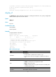
Do you want to convert the content of the next startup configuration file flash:/startup.cfg to make it available in stand-alone mode? [Y/N]:y Please wait... Saving the converted configuration file to the main board succeeded. display irf Use display irf to display IRF fabric information, including the member ID, role, priority, bridge MAC address, and description of each IRF member.
Field Description Description you have configured for the member device. • If no description is configured, this field displays a dashed line (-----). • If the description exceeds the maximum number of characters that can Description be displayed, an ellipsis (…) is displayed in place of the exceeding text. To display the complete description, use the display current-configuration command. Status of the software auto-update function: • yes—Enabled.
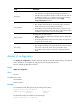
MemberID NewID IRF-Port1 1 1 2 2 IRF-Port2 FortyGigE1/8/0/1 disable FortyGigE1/8/0/2 disable FortyGigE2/8/0/1 FortyGigE2/8/0/2 Table 2 Command output Field Description Current member ID of the device. MemberID If no member ID is assigned, this field displays two hyphens (--). Member priority. Priority This field is displayed only when the device is operating in standalone mode. Member ID assigned to the device. This member ID takes effect at reboot.
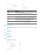
1 disable -- 2 FortyGigE2/8/0/1 UP FortyGigE2/8/0/2 UP FortyGigE2/8/0/3 DOWN FortyGigE2/8/0/4 ADM Table 3 Command output Field Description Member ID IRF member ID. IRF port number: IRF Port • 1—IRF-port 1. • 2—IRF-port 2. Physical ports bound to the IRF port. If no physical port has been bound to the IRF port, this field displays disable. Interface Link state of IRF physical ports: • UP—Link is up. • DOWN—Link is down.
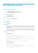
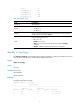
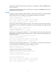
Figure 1 IRF topology Table 4 Command output Field Description IRF-Port 1 Information about IRF-port 1, including its link state and neighbor. IRF-Port 2 Information about IRF-port 2, including its link state and neighbor. Link state of the IRF port: Link • UP—IRF link is up. • DOWN—IRF link is down. • DIS—No physical ports have been bound to the IRF port. You must use the port group interface command to bind at least one physical port to the IRF port. • TIMEOUT—IRF hello interval has timed out.
To display the load sharing mode used on each IRF port in the IRF fabric, specify the irf-port keyword but not any IRF port. To display the load sharing mode used on a specific IRF port, specify both the irf-port keyword and the member-id/port-number argument. Examples # Display the global load sharing mode for IRF links. In this example, because no user-defined global load sharing mode has been configured, the default global load sharing mode applies.
Table 5 Command output Field Description Global load sharing mode for IRF links: irf-port Load-Sharing Mode • If no global IRF link load sharing mode has been configured, the default global load sharing mode applies. • If a user-defined global load sharing mode has been configured, the configured mode applies. Link load sharing mode of IRF-port 1/1: irf-port 1/1 Load-Sharing Mode • If you have not configured a port-specific load sharing mode, the global IRF link load sharing mode applies.
MAD LACP enabled. MAD BFD disabled. # Display detailed MAD information. display mad verbose Current MAD status: Detect Excluded ports(configurable): FortyGigE2/1/0/2 FortyGigE2/1/0/3 Excluded ports(can not be configured): FortyGigE1/9/0/1 FortyGigE1/9/0/2 FortyGigE1/9/0/3 FortyGigE1/9/0/4 FortyGigE2/9/0/1 FortyGigE2/9/0/2 FortyGigE2/9/0/3 FortyGigE2/9/0/4 MAD enabled aggregation port: Bridge-Aggregation2 MAD BFD enabled interface: Vlan-interface2 mad ip address 10.0.0.2 255.255.0.
Syntax irf auto-merge enable undo irf auto-merge enable Default This function is disabled. To complete an IRF merge, you must manually reboot the IRF fabric that has failed in the master election. Views System view Predefined user roles network-admin Usage guidelines To avoid an auto merge failure, make sure the auto merge function is enabled on both IRF fabrics that are merging. This command is available in IRF mode.
Usage guidelines This command is available in IRF mode. When you change the operating mode from IRF to standalone, the command configuration is lost, regardless of whether you have saved the configuration. To join an IRF fabric, a device must use the same software images as the master in the IRF fabric. When you add a device to the IRF fabric, software auto-update compares the startup software images of the device with the current software images of the IRF master.
Predefined user roles network-admin Parameters domain-id: Specifies a domain ID for the IRF fabric. The value range is 0 to 4294967295. Usage guidelines This command is available in IRF mode. When you change the operating mode from IRF to standalone, the IRF domain setting is lost, regardless of whether you have saved the configuration. One IRF fabric forms one IRF domain. IRF uses IRF domain IDs to uniquely identify IRF fabrics and prevent IRF fabrics from interfering with one another.
• When the IRF link changes from up to down, the port does not immediately report the change to the IRF fabric. If the IRF link state is still down when the delay time is reached, the port reports the change to the IRF fabric. • When the IRF link changes from down to up, the link layer immediately reports the event to the IRF fabric. HP recommends setting the delay to 0 seconds in one of the following situations: • The IRF fabric requires a quick master/subordinate or IRF link switchover.
By default, an IRF fabric uses the bridge MAC address of the master device as its bridge MAC address. Layer 2 protocols, such as LACP, use this bridge MAC address to identify the IRF fabric. On a switched LAN, the bridge MAC address must be unique. To avoid duplicate bridge MAC addresses, an IRF fabric can change its bridge MAC address automatically after its master leaves. However, the change causes temporary service disruption.
[Sysname] irf member 2 Info: Member ID change will take effect after the member reboots and operates in IRF mode. Related commands irf member renumber irf member description Use irf member description to configure a description for an IRF member. Use undo irf member description to restore the default. Syntax irf member member-id description text undo irf member member-id description Default No description is configured for any IRF member.
Default IRF member priority is 1. Views System view Predefined user roles network-admin Parameters member-id: Specifies an IRF member ID. The value range for this argument is 1 to 4. However, the specified IRF member ID can only be 1 or 2. priority: Sets priority in the range of 1 to 32. The greater the priority value, the higher the priority. A member with higher priority is more likely to be the master. Usage guidelines Change member priority assignment to affect the maser election result.
new-member-id: Assigns a new ID to the IRF member device. The value range for this argument is 1 to 4. However, the assigned IRF member ID must be 1 or 2. If you use 3 or 4, the 7900 IRF fabric cannot be set up. Usage guidelines CAUTION: In IRF mode, an IRF member ID change can invalidate member ID-related settings, including interface and file path settings, and cause data loss. Be sure you fully understand its impact on your live network.
Parameters priority: Specifies an IRF member priority value in the range of 1 to 32. Usage guidelines Member priority is used for role election. The greater the priority value, the higher the priority. A member with higher priority is more likely to be the master. The member priority configured in standalone mode takes effect after you enable IRF mode. To change the member priority of a device in IRF mode, use the irf member member-id priority priority command.
Usage guidelines The global IRF link load sharing mode applies to all IRF ports in the IRF fabric. You can configure the sharing mode to include a combination of multiple criteria for making traffic distribution decisions. For example, criteria could include source MAC address and IP address. The device displays an error message if it does not support a criterion combination. If you configure the global load sharing mode multiple times, the most recent configuration takes effect.
You can configure an IRF port-specific load sharing mode to include a combination of multiple criteria for making traffic distribution decisions. For example, criteria could include source MAC address and IP address. The device displays an error message if it does not support a criterion combination. If you configure the port-specific load sharing mode multiple times on an IRF port, the most recent configuration takes effect. An IRF port preferentially uses the port-specific load sharing mode.
irf-port port-number Use irf-port port-number to enter IRF port view in standalone mode. Use undo irf-port port-number to remove all port bindings on an IRF port in standalone mode. Syntax irf-port port-number undo irf-port port-number Views System view Predefined user roles network-admin Parameters port-number: Specifies an IRF port number, which must be 1 or 2.
• The configuration file that the device starts with contains IRF port bindings. • You are binding physical ports to an IRF port in up state. Examples To configure and activate IRF port 1/2: # Bind FortyGigE 1/1/0/2 to IRF port 1/2.
Usage guidelines You cannot use BFD MAD with LACP MAD. BFD MAD uses the BFD protocol for detecting multi-active collisions, and can work with or without intermediate devices. When you configure BFD MAD, follow these guidelines: Category BFD MAD VLAN Restrictions and guidelines • Do not enable BFD MAD on VLAN-interface 1. • If you are using an intermediate device, assign the ports of BFD MAD links to the BFD MAD VLAN on the device. • The IRF fabrics in a network must use different BFD MAD VLANs.
Predefined user roles network-admin Usage guidelines LACP MAD handles collisions differently than BFD MAD. To avoid conflicts, do not use LACP MAD together with BFD MAD. LACP MAD uses extended LACP packets for detecting multi-active collisions and requires an intermediate HP device that also supports LACP MAD packets. You must set up a dynamic link aggregation group that spans all IRF member devices between the IRF fabric and the intermediate device.
Predefined user roles network-admin Parameters interface-type interface-number: Specifies a port by its type and number. Usage guidelines MAD action is not configurable for IRF physical ports. When MAD detects that an IRF fabric has split into two or more identical active IRF fabrics, it sets one of the IRF fabrics to the Detect state and all other IRF fabrics to the Recovery state. • The Detect-state IRF fabric is active and can continue to forward traffic.
member member-id: Specifies an IRF member ID. Usage guidelines To use BFD MAD, configure a MAD IP address on a BFD MAD-enabled VLAN interface for each IRF member. Make sure all the MAD IP addresses are on the same subnet. To avoid problems, only use the mad ip address command to configure IP addresses on the BFD MAD-enabled VLAN interface. Do not configure an IP address with the ip address command or configure a VRRP virtual address on the BFD MAD-enabled VLAN interface.
Examples # Restore the normal MAD state of the IRF fabric in Recovery state. system-view [Sysname] mad restore This command will restore the device from multi-active conflict state. Continue? [Y/N]:Y Restoring from multi-active conflict state, please wait... port group interface Use port group interface to bind a physical port to an IRF port. Use undo port group interface to remove the binding of a physical port and an IRF port.
Examples # In standalone mode, bind port FortyGigE 1/0/1 to IRF-port 1. system-view [Sysname] irf-port 1 [Sysname-irf-port1] port group interface FortyGigE 1/0/1 # In IRF mode, bind port FortyGigE 1/1/0/1 to IRF-port 1 of member 1.
Support and other resources Contacting HP For worldwide technical support information, see the HP support website: http://www.hp.
Conventions This section describes the conventions used in this documentation set. Command conventions Convention Description Boldface Bold text represents commands and keywords that you enter literally as shown. Italic Italic text represents arguments that you replace with actual values. [] Square brackets enclose syntax choices (keywords or arguments) that are optional. { x | y | ... } Braces enclose a set of required syntax choices separated by vertical bars, from which you select one.
Network topology icons Represents a generic network device, such as a router, switch, or firewall. Represents a routing-capable device, such as a router or Layer 3 switch. Represents a generic switch, such as a Layer 2 or Layer 3 switch, or a router that supports Layer 2 forwarding and other Layer 2 features. Represents an access controller, a unified wired-WLAN module, or the switching engine on a unified wired-WLAN switch. Represents an access point.
Index CDIMPSW irf priority,17 C irf-port global load-sharing mode,18 chassis convert mode irf,1 irf-port load-sharing mode,19 D irf-port member-id/port-number,20 display irf,2 irf-port port-number,21 display irf configuration,3 irf-port-configuration active,21 display irf link,4 M display irf topology,5 mad bfd enable,22 display irf-port load-sharing mode,6 mad enable,23 display mad,8 mad exclude interface,24 Documents,29 mad ip address,25 I mad restore,26 irf auto-merge enable,9 P