HP FlexFabric 7900 Switch Series IRF Configuration Guide Part number: 5998-4280 Software version: Release 2109 Document version: 6W100-20140122
Legal and notice information © Copyright 2014 Hewlett-Packard Development Company, L.P. No part of this documentation may be reproduced or transmitted in any form or by any means without prior written consent of Hewlett-Packard Development Company, L.P. The information contained herein is subject to change without notice.
Contents IRF overview ································································································································································· 1 Hardware compatibility ···················································································································································· 1 IRF benefits ···········································································································································
Configuring a member device description ········································································································· 19 Configuring IRF link load sharing mode ············································································································· 20 Configuring IRF bridge MAC persistence ··········································································································· 21 Enabling software auto-update for system software image synch
IRF overview The HP Intelligent Resilient Framework (IRF) technology creates a large IRF fabric from multiple devices to provide data center class availability and scalability. IRF virtualization technology offers processing power, interaction, unified management, and uninterrupted maintenance of multiple devices. This book describes IRF concepts and guides you through the IRF setup procedure. Hardware compatibility An HP 7900 switch can form an IRF fabric only with devices in the same series.
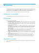
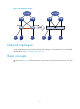
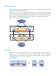
Figure 1 IRF application scenario Network topologies The HP 7900 IRF fabric only supports the daisy-chain topology. For information about connecting IRF member devices, see "Connecting physical IRF ports." Basic concepts This section uses Figure 2 to describe the basic concepts that you might encounter when you work with IRF.
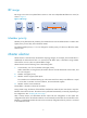
Figure 2 Two-chassis IRF fabric implementation schematic diagram Device A (MemberID=1) Device B (MemberID=2) MPU MPU IRF-port 2 IRF-port 1 IRF link Network FGE1/3/0/1 interfaces IRF physical port FGE2/3/0/1 Network IRF physical interfaces port An IRF fabric is formed. IRF Master (MemberID=1) IRF’s active MPU Subordinate (MemberID=2) IRF’s standby MPU In this figure, Device A and Device B form a two-chassis IRF fabric.
IRF member ID An IRF fabric uses member IDs to uniquely identify and manage its members. If two devices have the same IRF member ID, they cannot form an IRF fabric. If the IRF member ID of a device has been used in an IRF fabric, the device cannot join the fabric. Member ID information is included as the first part of interface numbers and file paths to uniquely identify interfaces and files in an IRF fabric.
IRF domain ID One IRF fabric forms one IRF domain. IRF uses IRF domain IDs to uniquely identify IRF fabrics and prevent IRF fabrics from interfering with one another. As shown in Figure 3, Device A and Device B form IRF fabric 1, and Device C and Device D form IRF fabric 2. Both fabrics use the LACP aggregate links between them for MAD. When a member device receives an extended LACP packet for MAD, it checks the domain ID to see whether the packet is from the local IRF fabric or from a different IRF fabric.
IRF merge IRF merge occurs when two split IRF fabrics reunite or when two independent IRF fabrics are united, as shown in Figure 5. Figure 5 IRF merge Member priority Member priority determines the possibility of a member device to be elected the master. A member with higher priority is more likely to be elected the master. The default member priority is 1. You can change the member priority of a device to affect the master election result.
IRF multi-active detection An IRF link failure causes an IRF fabric to split in two IRF fabrics operating with the same Layer 3 configurations, including the same IP address. To avoid IP address collision and network problems, IRF uses multi-active detection (MAD) mechanisms to detect the presence of multiple identical IRF fabrics, handle collisions, and recover from faults. Multi-active handling procedure The multi-active handling procedure includes detection, collision handling, and failure recovery.
Failure recovery To merge two split IRF fabrics, first repair the failed IRF link and remove the IRF link failure. If the IRF fabric in Recovery state fails before the failure is recovered, repair the failed IRF fabric and the failed IRF link. If the active IRF fabric fails before the failure is recovered, enable the inactive IRF fabric to take over the active IRF fabric. Then, recover the MAD failure.
BFD MAD BFD MAD can work with or without intermediate devices. Figure 7 shows a typical BFD MAD application scenario. To use BFD MAD: • Set up dedicated BFD MAD link between each pair of IRF members or between each IRF member and the intermediate device. Do not use the BFD MAD links for any other purpose. • Assign the ports connected by BFD MAD links to the same VLAN, create a VLAN interface for the VLAN, and assign a MAD IP address to each member on the VLAN interface.
Configuring IRF General restrictions and configuration guidelines To ensure a successful IRF setup, read the configuration restrictions and guidelines carefully before you connect and set up an IRF fabric. Software requirements All IRF member devices must run the same system software image version. IRF size and member ID restrictions To ensure a successful IRF setup, follow these IRF size and member ID restrictions: • An HP 7900 IRF fabric can have up to two chassis.
For more information about the binding mode, see "Binding physical ports to IRF ports" and "Adding physical ports to an IRF port." IRF port connecting restrictions When you connect two neighboring IRF members, connect the physical ports of IRF-port 1 on one member to the physical ports of IRF-port 2 on the other.
Other configuration guidelines When you configure an IRF fabric, you must also follow these guidelines: • If a subordinate device uses the same next-startup configuration file name as the master device, the file might be overwritten depending on your configuration file management settings. To continue to use the configuration file after removing the device from the IRF fabric, back up the file before setting up the IRF fabric.
Planning the IRF fabric setup Consider the following items when you plan an IRF fabric: • Hardware compatibility and restrictions • IRF fabric size • Master device • IRF physical ports • Member ID and priority assignment scheme • Fabric topology and cabling scheme For more information about hardware and cabling, see the installation guide for the device. Preconfiguring IRF member devices in standalone mode Perform the tasks in this section on every IRF member device.
Step Command Remarks 1. Enter system view. system-view N/A 2. Specify a priority for the device. irf priority priority The default IRF member priority is 1. Binding physical ports to IRF ports To establish an IRF connection between two devices, you must bind at least one physical port to IRF-port 1 on one device and to IRF-port 2 on the other. For link redundancy and load sharing, bind multiple physical ports to one IRF port. Make sure the IRF physical ports are operating as Layer 2 interfaces.
Task Command Save the running configuration to the next-startup configuration file. save [ safely ] [ backup | main ] [ force ] Connecting physical IRF ports When you connect two neighboring IRF members, connect the physical ports of IRF-port 1 on one member to the physical ports of IRF-port 2 on the other, as shown in Figure 8. IMPORTANT: No intermediate devices are allowed between neighboring members. Figure 8 Connecting IRF physical ports Connect the devices into a daisy-chain topology.
To set the operating mode of a device to IRF mode: Step Command Remarks 1. Enter system view. system-view N/A 2. Set the operating mode to IRF mode. chassis convert mode irf The default operating mode is standalone mode. After you change the operating mode, the device automatically reboots to commit the change. During the reboot, you may choose to have the system automatically convert the startup configuration file.
Step Command Remarks 1. Enter system view. system-view N/A 2. Assign a domain ID to the IRF fabric. irf domain domain-id By default, the domain ID of an IRF fabric is 0. Changing the member ID of a device CAUTION: • In IRF mode, an IRF member ID change can invalidate member ID-related settings and cause data loss. Be sure you fully understand its impact on your live network.
Adding physical ports to an IRF port An IRF port can have up to eight physical ports. In IRF mode, you can add more physical ports to an IRF port. This task does not affect the ongoing traffic on the IRF port. When you perform this task, follow the IRF physical port restrictions and configuration guidelines in "IRF physical port restrictions" and "Binding physical ports to IRF ports." To configure IRF ports: Step 1. Enter system view. Command Remarks system-view N/A • Enter interface range view: 2.
Step 11. Save the running configuration. 12. Activate the configuration on the IRF port. Command Remarks save Activating IRF port configurations can cause IRF merge and reboot. To avoid data loss, save the running configuration to the startup configuration file before you perform the operation. irf-port-configuration active After this step is performed, the state of the IRF port changes to UP, the member devices elect a master automatically, and the subordinate device reboots automatically.
Configuring IRF link load sharing mode On an IRF port, traffic is balanced across its physical links. You can configure the IRF port to distribute traffic based on any combination of the following criteria: • IP addresses • MAC addresses • Incoming ports If a criteria combination is not supported, the system displays an error message. Configure the IRF link load sharing mode for IRF links in system view or IRF port view: • In system view, the configuration is global and takes effect on all IRF ports.
Step Command Remarks The following are the default load sharing mode: • Non-IP traffic—Source and destination MAC addresses. Configure the port-specific load sharing mode. 3. • Non-TCP/-UDP IP irf-port load-sharing mode { destination-ip | destination-mac | ingress-port | source-ip | source-mac } * traffic—Source and destination IP addresses. • TCP/UDP IP traffic—Source and destination service ports. If you execute this command multiple times, the most recent configuration takes effect.
Step Command Remarks • Retain the bridge MAC address even if the master has changed: irf mac-address persistent always 2. Configure IRF bridge MAC persistence. • Preserve the bridge MAC address for 6 minutes after the master leaves: irf mac-address persistent timer By default, the IRF fabric's bridge MAC address is retained permanently even after the master leaves.
Configuration procedure To enable an IRF fabric to automatically synchronize software images of the master to the devices you are adding to the IRF fabric: Step Command Remarks 1. Enter system view. system-view N/A 2. Enable software auto-update. irf auto-update enable By default, this function is enabled. Setting the IRF link down report delay Link flapping causes frequent IRF splits and merges during a short time.
Table 1 A comparison of the MAD mechanisms MAD mechanism LACP MAD Advantages Disadvantages • Detection speed is fast. • Requires no MAD-dedicated physical ports or interfaces. Application scenario Requires an intermediate HP device that supports extended LACPDUs for MAD. Link aggregation is used between the IRF fabric and its upstream or downstream device. For information about LACP, see Layer 2—LAN Switching Configuration Guide. • No special requirements for network scenarios.
Step Command Remarks interface bridge-aggregation interface-number Perform this step also on the intermediate device. Configure the aggregation group to operate in dynamic aggregation mode. link-aggregation mode dynamic By default, an aggregation group operates in static aggregation mode. 5. Enable LACP MAD. mad enable By default, LACP MAD is disabled. 6. Return to system view. quit N/A 3. 4. Create a Layer 2 aggregate interface and enter aggregate interface view.
Category Restrictions and guidelines • Do not use the BFD MAD VLAN for any purpose other than configuring BFD BFD MAD VLAN and feature compatibility MAD. Layer 2 or Layer 3 features, including ARP and LACP, cannot work on the BFD MAD-enabled VLAN interface or any port in the VLAN. If you configure any other feature on the VLAN, neither the configured feature nor the BFD MAD function will work correctly. • Disable the spanning tree feature on any Layer 2 Ethernet ports in the BFD MAD VLAN.
Step Command Remarks 7. Return to system view. quit N/A 8. Enter VLAN interface view. interface vlan-interface interface-number N/A 9. Enable BFD MAD. mad bfd enable By default, BFD MAD is disabled. By default, no MAD IP address is configured on any VLAN interface. 10. Configure a MAD IP address for a member on the VLAN interface. mad ip address ip-address { mask | mask-length } member member-id Repeat this step to assign a MAD IP address to each member device on the VLAN interface.
Figure 10 Recovering the IRF fabric If the active IRF fabric has failed before the IRF link is recovered (see Figure 11), use the mad restore command on the inactive IRF fabric to change its MAD state to Detect. The command also brings up all physical ports that were shut down by MAD. After you repair the IRF link, the two parts merge into a unified IRF fabric. Figure 11 Active IRF fabric fails before the IRF link is recovered To manually recover an inactive IRF fabric: Step Command 1.
After the IRF fabric is recovered, all ports that have been shut down by MAD come up automatically. Displaying and maintaining an IRF fabric Execute display commands in any view. Task Command Display information about all IRF members. display irf Display the IRF fabric topology. display irf topology Display IRF link information. display irf link Display basic IRF settings. display irf configuration Display the load sharing mode for IRF links.
Figure 12 Network diagram Configuration procedure IMPORTANT: Between two neighboring IRF members, IRF links must be bound to IRF-port 1 on one member and to IRF-port 2 on the other. 1. Configure Device A: # Assign member ID 1 to Device A, and bind FortyGigE 1/0/2 to IRF-port 2. system-view [Sysname] irf member 1 Info: Member ID change will take effect after the member reboots and operates in IRF mode.
system-view [Sysname] irf member 2 Info: Member ID change will take effect after the member reboots and operates in IRF mode. [Sysname] irf-port 1 [Sysname-irf-port1] port group interface fortygige 1/0/1 [Sysname-irf-port1] quit # Save the configuration. [Sysname] quit save # Connect the two devices as shown in Figure 12. # Log in to Device B. (Details not shown.) # Enable IRF mode. system-view [Sysname] chassis convert mode irf The device will switch to IRF mode and reboot.
CAUTION: If the intermediate device is also an IRF fabric, assign the two IRF fabrics different domain IDs for correct split detection. False detection causes IRF split. # Create a dynamic aggregate interface. system-view [Sysname] interface bridge-aggregation 2 [Sysname-Bridge-Aggregation2] link-aggregation mode dynamic [Sysname-Bridge-Aggregation2] quit # Assign FortyGigE 1/0/1 and FortyGigE 1/0/2 to the aggregate interface.
Figure 13 Network diagram Configuration procedure 1. Configure IRF on Device A: # Assign member ID 1 to Device A. system-view [Sysname] irf member 1 Info: Member ID change will take effect after the member reboots and operates in IRF mode. # Enable IRF mode. [Sysname] chassis convert mode irf The device will switch to IRF mode and reboot. You are recommended to save the current running configuration and specify the configuration file for the next startup.
[Sysname] interface fortygige 1/1/0/2 [Sysname-FortyGigE1/1/0/2] undo shutdown [Sysname-FortyGigE1/1/0/2] quit # Save the running configuration to the startup configuration file. [Sysname] quit save 2. Configure IRF on Device B: # Assign member ID 2 to Device B. system-view [Sysname] irf member 2 Info: Member ID change will take effect after the member reboots and operates in IRF mode. # Enable IRF mode.
[Sysname] irf-port-configuration active %Jul 9 09:04:48:279 2013 STM/4/STM_MERGE_NEED_REBOOT: IRF merge occurs and the IRF system needs a reboot. %Jul 9 14:03:06:855 2013 STM/5/STM_MERGE: IRF merge occurs and the IRF system does not need to reboot. # Reboot Device B. [Sysname] quit reboot Device A and Device B form a two-chassis IRF fabric after Device B reboots. Device B is the subordinate device. 4. Configure BFD MAD: # Create VLAN 3, and add FortyGigE 1/1/0/1 and FortyGigE 2/1/0/1 to VLAN 3.
Figure 14 Network diagram Configuration procedure 1. Identify the master. display irf MemberID Slot Role CPU-Mac Description *+1 0 Master Priority 1 00e0-fc0a-15e0 DeviceA 2 0 Standby 1 00e0-fc0f-15e1 DeviceB -------------------------------------------------- * indicates the device is the master. + indicates the device through which the user logs in.
flash:/startup.cfg exists, overwrite? [Y/N]:y Validating file. Please wait..................................... The current configuration is saved to the active main board successfully. Configuration is saved to device successfully. 5. Change the operating mode of Device A to standalone. [IRF] undo chassis convert mode The device will switch to stand-alone mode and reboot. You are recommended to save the current running configuration and specify the configuration file for the next startup.
Support and other resources Contacting HP For worldwide technical support information, see the HP support website: http://www.hp.
Conventions This section describes the conventions used in this documentation set. Command conventions Convention Description Boldface Bold text represents commands and keywords that you enter literally as shown. Italic Italic text represents arguments that you replace with actual values. [] Square brackets enclose syntax choices (keywords or arguments) that are optional. { x | y | ... } Braces enclose a set of required syntax choices separated by vertical bars, from which you select one.
Network topology icons Represents a generic network device, such as a router, switch, or firewall. Represents a routing-capable device, such as a router or Layer 3 switch. Represents a generic switch, such as a Layer 2 or Layer 3 switch, or a router that supports Layer 2 forwarding and other Layer 2 features. Represents an access controller, a unified wired-WLAN module, or the switching engine on a unified wired-WLAN switch. Represents an access point.
Index A IRF BFD MAD (IRF mode), 25 accessing IRF bridge MAC persistence (IRF mode), 21 IRF fabric, 29 IRF fabric, 16 IRF global link load sharing mode, 20 active IRF LACP MAD, 29 IRF active MPU, 4 IRF LACP MAD (IRF mode), 24 adding IRF link load sharing mode (IRF mode), 20 IRF physical ports (IRF mode), 18 IRF MAD (IRF mode), 23 application scenario IRF member device (IRF mode), 16 IRF, 1 IRF member device description (IRF mode), 19 IRF BFD MAD, 9 IRF LACP MAD, 8 assigning IRF port-specif
IRF hardware compatibility, 1 IRF collision handling, 7 IRF configuration, 10, 12, 29 IRF device member priority (standalone mode), 13 IRF domain ID, 5 IRF fabric access, 16 IRF fabric domain ID assignment (IRF mode), 16 I ID IRF domain, 5 Intelligent Resilient Framework.
IRF link load sharing mode (IRF mode), 20 member device ID assignment (standalone mode), 13 member ID, 4 IRF port-specific load sharing mode (IRF mode), 20 local member ID restrictions, 10 member priority, 6 member priority change (IRF mode), 17 member roles, 3 merge, 6 merge restrictions, 11 IRF fabric access local login, 16 M MAC addressing IRF bridge MAC persistence (IRF mode), 21 MAD BFD.
IRF BFD MAD, 9 IRF physical port addition (IRF mode), 18 IRF BFD MAD configuration (IRF mode), 25 IRF physical port connection, 15 IRF domain ID, 5 IRF port shutdown exclusion, 27 IRF fabric recovery, 27 IRF port-specific load sharing mode (IRF mode), 20 IRF fabric setup, 13 physical port to IRF port bind (standalone mode), 14 IRF LACP MAD, 8 preconfiguring IRF LACP MAD configuration (IRF mode), 24 IRF link down report delay (IRF mode), 23 IRF member device (standalone mode), 13 priority IRF M
recovering IRF fabric, 27 IRF BFD MAD, 9 restoring IRF standalone mode, 35 IRF fabric, 5 saving IRF next startup configuration file (standalone mode), 14 IRF fabric recovery, 27 IRF LACP MAD, 8 setting IRF link down report delay (IRF mode), 23 IRF MAD, 7 IRF MAD detection, 7 setting IRF operating mode, 15 specifying IRF device member priority (standalone mode), 13 R IRF MAD handling procedure, 7 IRF master election, 6 standby IRF standby MPU, 4 recovering IRF fabric, 27 redundancy switching IRF m