HP FlexFabric 7900 Switch Series Layer 3 - IP Services Configuration Guide Part number: 5998-4282 Software version: Release 2109 Document version: 6W100-20140122
Legal and notice information © Copyright 2014 Hewlett-Packard Development Company, L.P. No part of this documentation may be reproduced or transmitted in any form or by any means without prior written consent of Hewlett-Packard Development Company, L.P. The information contained herein is subject to change without notice.
Contents Configuring ARP ··························································································································································· 1 Overview············································································································································································ 1 ARP message format ·······························································································································
IP address lease extension···································································································································· 23 DHCP message format··················································································································································· 24 DHCP options ································································································································································· 25 Co
Basic DHCP snooping configuration example ··································································································· 49 Option 82 configuration example ······················································································································· 50 Configuring DNS ······················································································································································· 52 Overview·······························
Verifying the configuration ··································································································································· 76 Support and other resources ····································································································································· 77 Contacting HP ································································································································································ 77 Subsc
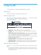
Configuring ARP This chapter describes how to configure the Address Resolution Protocol (ARP). Overview ARP resolves IP addresses into MAC addresses on Ethernet networks. ARP message format ARP uses two types of messages: ARP request and ARP reply. Figure 1 shows the format of ARP request/reply messages. Numbers in the figure refer to field lengths. Figure 1 ARP message format • Hardware type—Hardware address type. The value 1 represents Ethernet.
2. If Host A finds no entry for Host B, Host A buffers the packet and broadcasts an ARP request. The payload of the ARP request contains the following information: { Sender IP address and sender MAC address—Host A's IP address and MAC address. { Target IP address—Host B's IP address. { Target MAC address—An all-zero MAC address. All hosts on this subnet can receive the broadcast request, but only the requested host (Host B) processes the request. 3.
Static ARP entry A static ARP entry is manually configured and maintained. It does not age out and cannot be overwritten by any dynamic ARP entry. Static ARP entries protect communication between devices because attack packets cannot modify the IP-to-MAC mapping in a static ARP entry. The device supports the following types of static ARP entries: • Long static ARP entry—It contains the IP address, MAC address, VLAN, and output interface. It is directly used for forwarding packets.
Step 1. Enter system view. Command Remarks system-view N/A • Configure a long static ARP entry: 2. Configure a static ARP entry. arp static ip-address mac-address vlan-id interface-type interface-number • Configure a short static ARP entry: arp static ip-address mac-address Use either command. By default, no static ARP entry is configured. Configuring a multiport ARP entry A multiport ARP entry contains an IP address, MAC address, and VLAN ID.
Setting the maximum number of dynamic ARP entries for a device A device can dynamically learn ARP entries. To prevent a device from holding too many ARP entries, you can set the maximum number of dynamic ARP entries that the device can learn. When the maximum number is reached, the device stops learning ARP entries. If you set a value lower than the number of existing dynamic ARP entries, the device does not remove the existing entries unless they are aged out.
Setting the aging timer for dynamic ARP entries Each dynamic ARP entry in the ARP table has a limited lifetime, called an aging timer. The aging timer of a dynamic ARP entry is reset each time the dynamic ARP entry is updated. A dynamic ARP entry that is not updated before its aging timer expires is deleted from the ARP table. To set the aging timer for dynamic ARP entries: Step Command Remarks 1. Enter system view. system-view N/A 2. Set the aging timer for dynamic ARP entries.
Step 3. Specify the VLAN interface as a customer-side port. Command Remarks arp mode uni By default, a port operates as a network-side port. Enabling ARP logging This function enables a device to log ARP events in ARP resolution. To enable ARP logging: Step Command Remarks 1. Enter system view. system-view N/A 2. Enable ARP logging. arp check log enable By default, ARP logging is disabled.
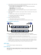
Configuration examples Static ARP configuration example Network requirements As shown in Figure 3, hosts are connected to the switch, which is connected to the router through interface FortyGigE 1/0/1 in VLAN 10. To ensure secure communications between the router and switch, configure a static ARP entry for the router on the switch. Figure 3 Network diagram Configuration procedure # Create VLAN 10. system-view [Switch] vlan 10 [Switch-vlan10] quit # Add interface FortyGigE 1/0/1 to VLAN 10.
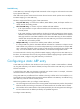
IP address MAC address VLAN Interface 192.168.1.1 00e0-fc01-0000 10 FGE1/0/1 Aging Type N/A S Multiport ARP entry configuration example Network requirements As shown in Figure 4, a switch connects to three servers through interfaces FortyGigE 1/0/1, FortyGigE 1/0/2, and FortyGigE 1/0/3 in VLAN 10. The servers share the IP address 192.168.1.1/24 and MAC address 00e0-fc01-0000. Configure a multiport ARP entry to send IP packets with destination IP address 192.168.1.1 to the three servers.
# Configure a multiport unicast MAC address entry that has MAC address 00e0-fc01-0000, and output interfaces FortyGigE 1/0/1, FortyGigE 1/0/2, and FortyGigE 1/0/3 in VLAN 10. [Switch] mac-address multiport 00e0-fc01-0000 interface fortygige 1/0/1 to fortygige 1/0/3 vlan 10 # Configure a multiport ARP entry with IP address 192.168.1.1 and MAC address 00e0-fc01-0000. [Switch] arp multiport 192.168.1.1 00e0-fc01-0000 10 # Display ARP information.
Configuring gratuitous ARP Overview In a gratuitous ARP packet, the sender IP address and the target IP address are the IP address of the sending device. A device sends a gratuitous ARP packet for either of the following purposes: • Determine whether its IP address is already used by another device. If the IP address is already used, the device is informed of the conflict by an ARP reply. • Inform other devices of a MAC address change.
{ { If the virtual IP address of the VRRP group is associated with a virtual MAC address, the sender MAC address in the gratuitous ARP packet is the virtual MAC address of the virtual router. If the virtual IP address of the VRRP group is associated with the real MAC address of an interface, the sender MAC address in the gratuitous ARP packet is the MAC address of the interface on the master router in the VRRP group.
To enable IP conflict notification: Step Command Remarks 1. Enter system view. system-view N/A 2. Enable IP conflict notification. arp ip-conflict log prompt By default, IP conflict notification is disabled.
Configuring proxy ARP Proxy ARP enables a device on one network to answer ARP requests for an IP address on another network. With proxy ARP, hosts on different broadcast domains can communicate with each other as they would on the same broadcast domain. Proxy ARP includes common proxy ARP and local proxy ARP. • Common proxy ARP—Allows communication between hosts that connect to different Layer-3 interfaces and reside in different broadcast domains.
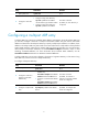
Task Command Display common proxy ARP status. display proxy-arp [ interface interface-type interface-number ] Display local proxy ARP status. display local-proxy-arp [ interface interface-type interface-number ] Common proxy ARP configuration example Network requirements As shown in Figure 5, Host A and Host D have the same IP prefix and mask, but they are located on different subnets separated by the switch (Host A belongs to VLAN 1, and Host D belongs to VLAN 2).
# Configure the IP address of VLAN-interface 2. [Switch] interface vlan-interface 2 [Switch-Vlan-interface2] ip address 192.168.20.99 255.255.255.0 # Enable common proxy ARP on VLAN-interface 2. [Switch-Vlan-interface2] proxy-arp enable After the configuration, Host A and Host D can ping each other.
Configuring IP addressing This chapter describes IP addressing basic and manual IP address assignment for interfaces. Dynamic IP address assignment (DHCP) is beyond the scope of this chapter. The IP addresses in this chapter refer to IPv4 addresses unless otherwise specified. NOTE: The term "interface" in this chapter collectively refers to Layer 3 interfaces, including VLAN interfaces and Layer 3 Ethernet interfaces.
Table 1 IP address classes and ranges Class Address range Remarks The IP address 0.0.0.0 is used by a host at startup for temporary communication. This address is never a valid destination address. A 0.0.0.0 to 127.255.255.255 B 128.0.0.0 to 191.255.255.255 N/A C 192.0.0.0 to 223.255.255.255 N/A D 224.0.0.0 to 239.255.255.255 Multicast addresses. E 240.0.0.0 to 255.255.255.255 Reserved for future use, except for the broadcast address 255.255.255.255.
For example, a Class B network without subnetting can accommodate 1022 more hosts than the same network subnetted into 512 subnets. • Without subnetting—65534 hosts (216 – 2). (The two deducted addresses are the broadcast address, which has an all-one host ID, and the network address, which has an all-zero host ID.) • With subnetting—Using the first nine bits of the host-id for subnetting provides 512 (29) subnets. However, only seven bits remain available for the host ID.
Task Command Display IP configuration and statistics for the specified or all Layer 3 interfaces. display ip interface [ interface-type interface-number ] Display brief IP configuration information for the specified or all Layer 3 interfaces. display ip interface [ interface-type [ interface-number ] ] brief IP address configuration example Network requirements As shown in Figure 8, a port in VLAN 1 on a switch is connected to a LAN comprising two segments: 172.16.1.0/24 and 172.16.2.0/24.
# Set the gateway address to 172.16.1.1 on the PCs attached to subnet 172.16.1.0/24, and to 172.16.2.1 on the PCs attached to subnet 172.16.2.0/24. Verifying the configuration # Ping a host on subnet 172.16.1.0/24 from the switch to check the connectivity. ping 172.16.1.2 Ping 172.16.1.2 (172.16.1.2): 56 data bytes, press CTRL_C to break 56 bytes from 172.16.1.2: icmp_seq=0 ttl=128 time=7.000 ms 56 bytes from 172.16.1.2: icmp_seq=1 ttl=128 time=2.000 ms 56 bytes from 172.16.1.
DHCP overview The Dynamic Host Configuration Protocol (DHCP) provides a framework to assign configuration information to network devices. Figure 9 shows a typical DHCP application scenario where the DHCP clients and the DHCP server reside on the same subnet. The DHCP clients can also obtain configuration parameters from a DHCP server on another subnet through a DHCP relay agent. For more information about the DHCP relay agent, see "Configuring the DHCP relay agent.
IP address allocation process Figure 10 IP address allocation process 1. The client broadcasts a DHCP-DISCOVER message to locate a DHCP server. 2. Each DHCP server offers configuration parameters such as an IP address to the client in a DHCP-OFFER message. The sending mode of the DHCP-OFFER is determined by the flag field in the DHCP-DISCOVER message. For related information, see "DHCP message format." 3.
DHCP message format Figure 11 shows the DHCP message format. DHCP uses some of the fields in significantly different ways. The numbers in parentheses indicate the size of each field in bytes. Figure 11 DHCP message format • op—Message type defined in options field. 1 = REQUEST, 2 = REPLY • htype, hlen—Hardware address type and length of the DHCP client. • hops—Number of relay agents a request message traveled.
DHCP options DHCP uses the same message format as BOOTP, but DHCP uses the options field to carry information for dynamic address allocation and provide additional configuration information to clients. Figure 12 DHCP option format Common DHCP options The following are common DHCP options: • Option 3—Router option. It specifies the gateway address. • Option 6—DNS server option. It specifies the DNS server's IP address. • Option 33—Static route option.
The DHCP client can obtain the following information through Option 43: • ACS parameters, including the ACS URL, username, and password. • Service provider identifier, which is acquired by the CPE from the DHCP server and sent to the ACS for selecting vender-specific configurations and parameters. • PXE server address, which is used to obtain the boot file or other control information from the PXE server. 1.
Relay agent option (Option 82) Option 82 is the relay agent option. It records the location information about the DHCP client. When a DHCP relay agent or DHCP snooping device receives a client's request, it adds Option 82 to the request message and sends it to the server. The administrator can use Option 82 to locate the DHCP client and further implement security control and accounting. The DHCP server can use Option 82 to provide individual configuration policies for the clients.
• RFC 3046, DHCP Relay Agent Information Option • RFC 3442, The Classless Static Route Option for Dynamic Host Configuration Protocol (DHCP) version 4 28
Configuring the DHCP relay agent Overview The DHCP relay agent enables clients to get IP addresses from a DHCP server on another subnet. This feature avoids deploying a DHCP server for each subnet to centralize management and reduce investment. Figure 16 shows a typical application of the DHCP relay agent. Figure 16 DHCP relay agent application NOTE: The term "interface" in this section collectively refers to Layer 3 interfaces, including VLAN interfaces and Layer 3 Ethernet interfaces.
Figure 17 DHCP relay agent operation DHCP relay agent support for Option 82 Option 82 records the location information about the DHCP client. It enables the administrator to locate the DHCP client for security and accounting purposes, and to assign IP addresses in a specific range to clients. For more information, see "Relay agent option (Option 82)." If the DHCP relay agent supports Option 82, it handles DHCP requests by following the strategies described in Table 2.
Tasks at a glance (Optional.) Configuring the DHCP relay agent to release an IP address (Optional.) Configuring Option 82 (Optional.) Setting the DSCP value for DHCP packets sent by the DHCP relay agent Enabling DHCP You must enable DHCP to validate other DHCP relay agent settings. To enable DHCP: Step Command Remarks 1. Enter system view. system-view N/A 2. Enable DHCP. dhcp enable By default, DHCP is disabled.
To specify a DHCP server address on a relay agent: Step Command Remarks 1. Enter system view. system-view N/A 2. Enter interface view. interface interface-type interface-number N/A 3. Specify a DHCP server address on the relay agent. dhcp relay server-address ip-address By default, no DHCP server address is specified on the relay agent.
Step Command Remarks 2. Enable periodic refresh of dynamic relay entries. dhcp relay client-information refresh enable By default, periodic refresh of dynamic relay entries is enabled. 3. Configure the refresh interval. dhcp relay client-information refresh [ auto | interval interval ] By default, the refresh interval is auto, which is calculated based on the number of total relay entries.
Configuring the DHCP relay agent to release an IP address Configure the relay agent to release the IP address for a relay entry. The relay agent sends a DHCP-RELEASE message to the server and meanwhile deletes the relay entry. Upon receiving the DHCP-RELEASE message, the DHCP server releases the IP address. To configure the DHCP relay agent to release an IP address: Step Command Remarks 1. Enter system view. system-view N/A 2. Configure the DHCP relay agent to release an IP address.
Setting the DSCP value for DHCP packets sent by the DHCP relay agent The DSCP value of a packet specifies the priority level of the packet and affects the transmission priority of the packet. To set the DSCP value for DHCP packets sent by the DHCP relay agent: Step Command Remarks 1. Enter system view. system-view N/A 2. Set the DSCP value for DHCP packets sent by the DHCP relay agent. dhcp dscp dscp-value By default, the DSCP value in DHCP packets sent by the DHCP relay agent is 56.
The DHCP relay agent and server are on different subnets, so configure static or dynamic routing to make them reachable to each other. Perform the configuration on the DHCP server to guarantee the client-server communication. Figure 18 Network diagram Configuration procedure # Specify IP addresses for the interfaces. (Details not shown.) # Enable DHCP. system-view [SwitchA] dhcp enable # Enable the DHCP relay agent on VLAN-interface 10.
Configuration procedure # Specify IP addresses for the interfaces. (Details not shown.) # Enable DHCP. system-view [SwitchA] dhcp enable # Enable the DHCP relay agent on VLAN-interface 10. [SwitchA] interface vlan-interface 10 [SwitchA-Vlan-interface10] dhcp select relay # Specify the IP address of the DHCP server. [SwitchA-Vlan-interface10] dhcp relay server-address 10.1.1.1 # Configure the handling strategies and padding content of Option 82.
Configuring the DHCP client With DHCP client enabled, an interface uses DHCP to obtain configuration parameters from the DHCP server, for example, an IP address. The DHCP client configuration is supported only on Layer 3 Ethernet interfaces (including management Ethernet interfaces) and VLAN interfaces. When multiple VLAN interfaces with the same MAC address use DHCP for IP address acquisition through a relay agent, the DHCP server cannot be a Windows Server 2000 or Windows Server 2003.
Step 2. 3. Command Remarks Enter interface view. interface interface-type interface-number N/A Configure a DHCP client ID for the interface. dhcp client identifier { ascii string | hex string | mac interface-type interface-number } By default, an interface generates the DHCP client ID based on its MAC address. If the interface has no MAC address, it uses the MAC address of the first Ethernet interface to generate its client ID. DHCP client ID includes ID type and type value.
Step 2. Set the DSCP value for DHCP packets sent by the DHCP client. Command Remarks dhcp client dscp dscp-value By default, the DSCP value in DHCP packets sent by the DHCP client is 56. Displaying and maintaining the DHCP client Execute display command in any view. Task Command Display DHCP client information.
Configuring DHCP snooping DHCP snooping works between the DHCP client and server, or between the DHCP client and DHCP relay agent. It guarantees that DHCP clients obtain IP addresses from authorized DHCP servers. Also, it records IP-to-MAC bindings of DHCP clients (called DHCP snooping entries) for security purposes. DHCP snooping does not work between the DHCP server and DHCP relay agent.
Figure 20 Trusted and untrusted ports In a cascaded network as shown in Figure 21, configure each DHCP snooping device's ports connected to other DHCP snooping devices as trusted ports. To save system resources, you can disable the untrusted ports that are not directly connected to DHCP clients from generating DHCP snooping entries.
Table 3 Handling strategies If a DHCP request has… Option 82 No Option 82 Handling strategy DHCP snooping… Drop Drops the message. Keep Forwards the message without changing Option 82. Replace Forwards the message after replacing the original Option 82 with the Option 82 padded according to the configured padding format, padding content, and code type. N/A Forwards the message after adding the Option 82 padded according to the configured padding format, padding content, and code type.
Step Command Remarks 1. Enter system view. system-view N/A 2. Enable DHCP snooping. dhcp snooping enable By default, DHCP snooping is disabled. 3. Enter interface view of a layer 2 Ethernet interface or a layer 2 aggregate interface. interface interface-type interface-number This interface must connect to the DHCP server. 4. Specify the port as a trusted port. dhcp snooping trust By default, all ports are untrusted ports after DHCP snooping is enabled. 5. Return to system view.
Step Command Remarks 5. (Optional.) Configure the padding content and code type for the Circuit ID sub-option. dhcp snooping information circuit-id { [ vlan vlan-id ] string circuit-id | { normal | verbose [ node-identifier { mac | sysname | user-defined node-identifier } ] } [ format { ascii | hex } ] } By default, the padding format is normal and the code type is hex for the Circuit ID sub-option. 6. (Optional.) Configure the padding content and code type for the Remote ID sub-option.
Step Command Remarks The default setting is 300 seconds. (Optional.) Set the amount of time to wait after a DHCP snooping entry changes before updating the database file. 4. dhcp snooping binding database update interval seconds When a DHCP snooping entry is learned or removed, the device does not update the database file until after the specified waiting period. All changed entries during that period will be updated.
Attackers can also forge DHCP-DECLINE or DHCP-RELEASE packets to terminate leases for legitimate DHCP clients that still need the IP addresses. To prevent such attacks, you can enable DHCP-REQUEST check. This feature uses DHCP snooping entries to check incoming DHCP-REQUEST messages. If a matching entry is found for a message, this feature compares the entry with the message information. If they are consistent, the message is considered as valid and forwarded to the DHCP server.
Step Command Remarks 1. Enter system view. system-view N/A 2. Enter interface view of a layer 2 Ethernet interface or a layer 2 aggregate interface. interface interface-type interface-number N/A By default, incoming DHCP packets are not rate limited. You can configure this command only on Layer 2 Ethernet interfaces and Layer 2 aggregate interfaces. 3. Configure the maximum rate at which the interface can receive DHCP packets.
Task Command Remarks Clear DHCP packet statistics on the DHCP snooping device (distributed devices–centralized IRF devices–in standalone mode). reset dhcp snooping packet statistics [ slot slot-number ] Available in user view. Clear DHCP packet statistics on the DHCP snooping device (distributed devices–in IRF mode). reset dhcp snooping packet statistics [ chassis chassis-number slot slot-number ] Available in user view.
Verifying the configuration The DHCP client can obtain an IP address and other configuration parameters only from the authorized DHCP server. You can display the DHCP snooping entry recorded for the client by using the display dhcp snooping binding command. Option 82 configuration example Network requirements As shown in Figure 23, enable DHCP snooping and configure Option 82 on the switch as follows: • Configure the handling strategy for DHCP requests that contain Option 82 as replace.
[Switch] interface FortyGigE 1/0/3 [Switch-FortyGigE1/0/3] dhcp snooping information enable [Switch-FortyGigE1/0/3] dhcp snooping information strategy replace [Switch-FortyGigE1/0/3] dhcp snooping information circuit-id verbose node-identifier sysname format ascii [Switch-FortyGigE1/0/3] dhcp snooping information remote-id string device001 Verifying the configuration Use the display dhcp snooping information command to display Option 82 configuration information on FortyGigE 1/0/2 and FortyGigE 1/0/3 on th
Configuring DNS Overview Domain Name System (DNS) is a distributed database used by TCP/IP applications to translate domain names into IP addresses. With DNS, you can use easy-to-remember domain names in some applications and let the DNS server translate them into correct IP addresses. The domain name-to-IP address mapping is called a DNS entry. DNS services can be static or dynamic. After a user specifies a name, the device checks the static name resolution table for an IP address.
Figure 24 shows the relationship between the user program, DNS client, and DNS server. The DNS client is made up of the resolver and cache. The user program and DNS client can run on the same device or different devices, but the DNS server and the DNS client usually run on different devices. Dynamic domain name resolution allows the DNS client to store latest DNS entries in the dynamic domain name cache.
Configuring the IPv4 DNS client Configuring static domain name resolution Static domain name resolution allows applications such as Telnet to contact hosts by using host names instead of IPv4 addresses. Follow these guidelines when you configure static domain name resolution: • Each host name maps to only one IPv4 address. The most recent configuration for a host name takes effect. • You can configure a maximum of 1024 host name-to-IPv4 address mappings.
Step 2. Specify a DNS server IPv4 address. 3. (Optional.) Configure a DNS suffix. Command Remarks dns server ip-address By default, no DNS server IPv4 address is specified. dns domain domain-name By default, no DNS suffix is configured and only the provided domain name is resolved. Specifying the source interface for DNS packets By default, the device uses the primary IP address of the output interface of the matching route as the source IP address of a DNS request.
Step 2. Command Specify the DNS trusted interface. Remarks dns trust-interface interface-type interface-number By default, no DNS trusted interface is specified. You can configure up to 128 DNS trusted interfaces. Setting the DSCP value for outgoing DNS packets The DSCP value of a packet specifies the priority level of the packet and affects the transmission priority of the packet. A bigger DSCP value represents a higher priority.
Figure 25 Network diagram Configuration procedure # Configure a mapping between host name host.com and IP address 10.1.1.2. system-view [Sysname] ip host host.com 10.1.1.2 # Use the ping host.com command to verify that the device can use static domain name resolution to resolve domain name host.com into IP address 10.1.1.2. [Sysname] ping host.com Ping host.com (10.1.1.2): 56 data bytes, press CTRL_C to break 56 bytes from 10.1.1.2: icmp_seq=0 ttl=255 time=1.000 ms 56 bytes from 10.1.1.
Configuration procedure Before performing the following configuration, make sure the device and the host can reach each other, and that the IP addresses of the interfaces are configured as shown in Figure 26. 1. Configure the DNS server: The configuration might vary with DNS servers. The following configuration is performed on a PC running Windows Server 2000. a. Select Start > Programs > Administrative Tools > DNS. The DNS server configuration page appears, as shown in Figure 27. b.
Figure 28 Adding a host d. On the page that appears, enter host name host and IP address 3.1.1.1. e. Click Add Host. The mapping between the IP address and host name is created. Figure 29 Adding a mapping between domain name and IP address 2.
# Specify the DNS server 2.1.1.2. system-view [Sysname] dns server 2.1.1.2 # Specify com as the name suffix. [Sysname] dns domain com Verifying the configuration # Use the ping host command on the device to verify that the communication between the device and the host is normal and that the translated destination IP address is 3.1.1.1. [Sysname] ping host Ping host.com (3.1.1.1): 56 data bytes, press CTRL_C to break 56 bytes from 3.1.1.1: icmp_seq=0 ttl=255 time=1.000 ms 56 bytes from 3.1.1.
Basic IP forwarding on the device Upon receiving a packet, the device uses the destination IP address of the packet to find a match from the forwarding information base (FIB) table, and then uses the matching entry to forward the packet. FIB table A device selects optimal routes from the routing table, and puts them into the FIB table. Each FIB entry specifies the next hop IP address and output interface for packets destined for a specific subnet or host.
Task Command Display FIB entries.
Configuring load sharing Overview If a routing protocol finds multiple equal-cost best routes to the same destination, the device forwards packets over the equal-cost routes to implement load sharing.
Figure 30 Network diagram Configuration procedure # On Switch A, assign FortyGigE 1/0/5 to VLAN 10, and FortyGigE 1/0/6 to VLAN 20. system-view [SwitchA] vlan 10 [SwitchA-vlan10] port fortygige 1/0/5 [SwitchA-vlan10] quit [SwitchA] vlan 20 [SwitchA-vlan20] port fortygige 1/0/6 [SwitchA-vlan20] quit # On Switch A, configure IP addresses for VLAN-interface 10 and VLAN-interface 20. [SwitchA] interface vlan-interface 10 [SwitchA-Vlan-interface10] ip address 10.1.1.
Destination count: 1 FIB entry count: 2 Flag: U:Useable G:Gateway R:Relay F:FRR H:Host B:Blackhole D:Dynamic S:Static Destination/Mask Nexthop Flag OutInterface/Token Label 1.2.3.0/24 10.1.1.2 USGR Vlan10 Null 1.2.3.0/24 20.1.1.2 USGR Vlan20 Null # On Switch A, configure per-flow load sharing based on the source IP address and destination IP address.
Optimizing IP performance A customized configuration can help optimize overall IP performance. This chapter describes various techniques you can use to customize your installation. NOTE: The term "interface" in this chapter collectively refers to Layer 3 interfaces, including VLAN interfaces and Layer 3 Ethernet interfaces. You can set an Ethernet port as a Layer 3 interface by using the port link-mode route command (see Layer 2—LAN Switching Configuration Guide).
Configuration example Network requirements As shown in Figure 31, the default gateway of the host is the IP address 1.1.1.2/24 of VLAN-interface 3 of the switch. Enable VLAN-interface 2 to forward directed broadcasts destined for the directly connected network. The server can receive directed broadcasts from the host to IP address 2.2.2.255. Figure 31 Network diagram Configuration procedure # Specify an IP address for VLAN-interface 3.
Configuring TCP path MTU discovery IMPORTANT: All the devices on a TCP connection must be enabled to send ICMP error messages by using the ip unreachables enable command. TCP path MTU discovery (in RFC 1191) discovers the path MTU between the source and destination ends of a TCP connection. It works as follows: 1. A TCP source device sends a packet with the Don't Fragment (DF) bit set. 2.
Enabling TCP SYN Cookie A TCP connection is established through a three-way handshake: 1. The sender sends a SYN packet to the server. 2. The server receives the SYN packet, establishes a TCP semi-connection in SYN_RECEIVED state, and replies with a SYN ACK packet to the sender. 3. The sender receives the SYN ACK packet and replies with an ACK packet. A TCP connection is established. An attacker can exploit this mechanism to mount SYN Flood attacks.
Step Command Remarks • Configure the TCP SYN wait timer: 2. Configure TCP timers. tcp timer syn-timeout time-value • Configure the TCP FIN wait timer: tcp timer fin-timeout time-value By default: • The TCP SYN wait timer is 75 seconds. • The TCP FIN wait timer is 675 seconds. Enabling sending ICMP error messages Perform this task to enable sending ICMP error messages, including redirect, time-exceeded, and destination unreachable messages.
{ { If the source uses Strict Source Routing to send packets, but the intermediate device finds that the next hop specified by the source is not directly connected, the device sends the source a Source Routing Failure ICMP error message. If the MTU of the sending interface is smaller than the packet and the packet has DF set, the device sends the source a Fragmentation Needed and DF-set ICMP error message. To enable sending ICMP error messages: Step 1. Enter system view.
To configure rate limit for ICMP error messages: Step 1. 2. Enter system view. Set the interval and bucket size for ICMP error messages Command Remarks system-view N/A ip icmp error-interval milliseconds [ bucketsize ] By default, the bucket allows a maximum of 10 tokens, and tokens are placed in the bucket at the interval of 100 milliseconds. To disable the ICMP rate limit, set the interval to 0 milliseconds.
Task Command Display brief information about TCP connections (in IRF mode). display tcp [ chassis chassis-number slot slot-number ] Display detailed information about TCP connections (in standalone mode). display tcp verbose [ slot slot-number [ pcb pcb-index ] ] Display detailed information about TCP connections (in IRF mode). display tcp verbose [ chassis chassis-number slot slot-number [ pcb pcb-index ] ] Display brief information about UDP connections (in standalone mode).
Configuring UDP helper Overview UDP helper enables a device to convert received UDP broadcast packets into unicast packets and forward them to a specific server. UDP helper is suitable for the scenario where hosts cannot obtain configuration information or device names by broadcasting packets because the target server or host resides on another broadcast domain. Upon receiving a UDP broadcast packet (the destination address is 255.255.255.
Step Command Remarks 3. Specify a UDP port. udp-helper port { port-number | dns | netbios-ds | netbios-ns | tacacs | tftp | time } By default, no UDP port is specified. 4. Enter interface view. interface interface-type interface-number N/A 5. Specify a destination server. udp-helper server ip-address By default, no destination server is specified. Displaying and maintaining UDP helper Execute display command in any view and reset command in user view.
# Enable UDP helper to forward broadcast packets with the UDP destination port 55. [SwitchA] udp-helper port 55 # Specify the destination server 10.2.1.1 on VLAN-interface 1. [SwitchA] interface vlan-interface 1 [SwitchA-Vlan-interface1] ip address 10.110.1.1 16 [SwitchA-Vlan-interface1] udp-helper server 10.2.1.1 # Enable the interface to receive directed broadcasts destined for the directly connected network.
Support and other resources Contacting HP For worldwide technical support information, see the HP support website: http://www.hp.
Conventions This section describes the conventions used in this documentation set. Command conventions Convention Description Boldface Bold text represents commands and keywords that you enter literally as shown. Italic Italic text represents arguments that you replace with actual values. [] Square brackets enclose syntax choices (keywords or arguments) that are optional. { x | y | ... } Braces enclose a set of required syntax choices separated by vertical bars, from which you select one.
Network topology icons Represents a generic network device, such as a router, switch, or firewall. Represents a routing-capable device, such as a router or Layer 3 switch. Represents a generic switch, such as a Layer 2 or Layer 3 switch, or a router that supports Layer 2 forwarding and other Layer 2 features. Represents an access controller, a unified wired-WLAN module, or the switching engine on a unified wired-WLAN switch. Represents an access point.
Index ACDEFILOPRSTU DHCP snooping configuration examples,49 A DHCP snooping configuration task list,43 Assigning an IP address to an interface,19 Disabling forwarding ICMP fragments,71 C Displaying and maintaining ARP,7 Common proxy ARP configuration example,15 Displaying and maintaining DHCP snooping,48 Configuration examples,8 Displaying and maintaining IP addressing,19 Configuration guidelines,74 Displaying and maintaining IP performance optimization,72 Configuration procedure,74 Displaying
Setting the DSCP value for DHCP packets sent by the DHCP client,39 L Load sharing configuration example,63 O Setting the DSCP value for DHCP packets sent by the DHCP relay agent,35 Overview,74 Setting the DSCP value for outgoing DNS packets,56 Overview,29 Setting the maximum number of DHCP snooping entries,47 Overview,52 Setting the maximum number of dynamic ARP entries for a device,5 Overview,41 Overview,1 Setting the maximum number of dynamic ARP entries for an interface,5 Overview,63 Overview,