HP FlexFabric 7900 Switch Series Security Configuration Guide Part number: 5998-4286 Software version: Release 2109 Document version: 6W100-20140122
Legal and notice information © Copyright 2014 Hewlett-Packard Development Company, L.P. No part of this documentation may be reproduced or transmitted in any form or by any means without prior written consent of Hewlett-Packard Development Company, L.P. The information contained herein is subject to change without notice.
Contents Configuring AAA ························································································································································· 1 Overview············································································································································································ 1 RADIUS ·············································································································································
Password control configuration task list ······················································································································· 51 Enabling password control ··········································································································································· 51 Setting global password control parameters ·············································································································· 52 Setting user group pas
IPsec configuration examples········································································································································ 85 Configuring a manual mode IPsec tunnel for IPv4 packets ·············································································· 85 Configuring an IKE-based IPsec tunnel for IPv4 packets ··················································································· 88 Configuring IKE ···············································
Working with SFTP files ······································································································································ 120 Displaying help information ······························································································································· 120 Terminating the connection with the SFTP server ····························································································· 121 Configuring the device as an SCP client ···
Entering FIPS mode ············································································································································· 165 Configuration changes in FIPS mode ················································································································ 166 Exiting FIPS mode ················································································································································ 167 FIPS self-tests ············
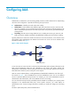
Configuring AAA Overview Authentication, Authorization, and Accounting (AAA) provides a uniform framework for implementing network access management. It specifies the following security functions: • Authentication—Identifies users and verifies their validity. • Authorization—Grants different users different rights and controls their access to resources and services.
RADIUS Remote Authentication Dial-In User Service (RADIUS) is a distributed information interaction protocol that uses a client/server model. It can protect networks against unauthorized access and is often used in network environments that require both high security and remote user access. The RADIUS authorization process is combined with the RADIUS authentication process, and user authorization information is piggybacked in authentication responses.
Basic RADIUS packet exchange process Figure 3 illustrates the interactions between a user host, the RADIUS client, and the RADIUS server. Figure 3 Basic RADIUS packet exchange process RADIUS uses in the following workflow: 1. The host sends a connection request that includes the user's username and password to the RADIUS client. 2. The RADIUS client sends an authentication request (Access-Request) to the RADIUS server.
RADIUS packet format RADIUS uses UDP to transmit packets. To ensure smooth packet exchange between the RADIUS server and the client, RADIUS uses a series of mechanisms, including the timer mechanism, the retransmission mechanism, and the backup server mechanism. Figure 4 shows the RADIUS packet format. Figure 4 RADIUS packet format Descriptions of the fields are as follows: The Code field (1 byte long) indicates the type of the RADIUS packet. Table 1 gives the main values and their meanings.
• The Authenticator field (16 bytes long) is used to authenticate responses from the RADIUS server and to encrypt user passwords. There are two types of authenticators: request authenticator and response authenticator. • The Attributes field (variable in length) includes specific authentication, authorization, and accounting information. This field can contain multiple attributes, each with three sub-fields: { Type—Type of the attribute.
No. Attribute No.
Figure 5 Format of attribute 26 HWTACACS HW Terminal Access Controller Access Control System (HWTACACS) is an enhanced security protocol based on TACACS (RFC 1492). HWTACACS is similar to RADIUS, and uses a client/server model for information exchange between the NAS and the HWTACACS server. HWTACACS typically provides AAA services for PPP, VPDN, and terminal users. In a typical HWTACACS scenario, terminal users need to log in to the NAS.
Figure 6 Basic HWTACACS packet exchange process for a Telnet user Host HWTACACS client HWTACACS server 1) The user tries to log in 2) Start-authentication packet 3) Authentication response requesting the username 4) Request for username 5) The user enters the username 6) Continue-authentication packet with the username 7) Authentication response requesting the password 8) Request for password 9) The user enters the password 10) Continue-authentication packet with the password 11) Response indicating succ
9. The user enters the password. 10. After receiving the login password, the HWTACACS client sends the HWTACACS server a continue-authentication packet that includes the login password. 11. If the authentication succeeds, the HWTACACS server sends back an authentication response to indicate that the user has passed authentication. 12. The HWTACACS client sends a user authorization request packet to the HWTACACS server. 13.
AAA methods AAA supports configuring different authentication, authorization, and accounting methods for different types of users in an ISP domain. The NAS determines the ISP domain and access type of a user, and uses the methods configured for the access type in the domain to control the user's access. AAA also supports configuring a set of default methods for an ISP domain. These default methods are used for users for whom no specific AAA methods are configured.
authorization is enabled, command accounting enables the accounting server to record all authorized commands. For more information about command accounting, see Fundamentals Configuration Guide. User role authentication—Authenticates each user who wants to obtain a temporary user role without logging out or getting disconnected. For more information about temporary user role authorization, see Fundamentals Configuration Guide.
No. Attribute Description 26 Vendor-Specific Vendor specific, proprietary attribute. A packet can contain one or more proprietary attributes, each of which can contain one or more sub-attributes. 27 Session-Timeout Maximum service duration for the user before termination of the session. 28 Idle-Timeout Maximum idle time permitted for the user before termination of the session. 31 Calling-Station-Id User identification that the NAS sends to the server.
HP proprietary RADIUS sub-attributes No. Sub-attribute Description 1 Input-Peak-Rate Peak rate in the direction from the user to the NAS, in bps. 2 Input-Average-Rate Average rate in the direction from the user to the NAS, in bps. 3 Input-Basic-Rate Basic rate in the direction from the user to the NAS, in bps. 4 Output-Peak-Rate Peak rate in the direction from the NAS to the user, in bps. 5 Output-Average-Rate Average rate in the direction from the NAS to the user, in bps.
No. Sub-attribute Description 141 Security_Level Security level assigned after the SSL VPN user passes security authentication. 201 Input-Interval-Octets Number of bytes input within a real-time accounting interval. 202 Output-Interval-Octets Number of bytes output within a real-time accounting interval. 203 Input-Interval-Packets Number of packets input within an accounting interval in the unit set on the NAS.
Figure 8 AAA configuration procedure To configure AAA, perform the following tasks: Tasks at a glance (Required.) Perform at least one of the following tasks to configure local users or AAA schemes: • Configuring local users • Configuring RADIUS schemes • Configuring HWTACACS schemes (Required.) Configure AAA methods for ISP domains: (Required.) Creating an ISP domain 1. 2. (Optional.) Configuring ISP domain attributes 3. (Required.
Configuring local users To implement local authentication, authorization, and accounting, create local users and configure user attributes on the device. The local users and attributes are stored in the local user database on the device. A local user is uniquely identified by the combination of a username and a user type. The device supports only device management users who log in to the device for device management.
Configuring local user attributes Follow these guidelines when you configure local user attributes: • When you use the password-control enable command to globally enable the password control feature, local user passwords are not displayed. • The authentication mode of user interfaces is set by the authentication-mode command in user line view and affects access to commands for login users. In AAA (scheme) mode, the authorized user role determines the commands available for each login user.
Step Command Remarks By default, the number of concurrent logins is not limited for the local user. 6. (Optional.) Set the upper limit of concurrent logins using the local user name. access-limit max-user-number This command takes effect only when local accounting is configured for the local user. It does not apply to FTP users, who do not support accounting. The following default settings apply: • No authorization ACL, idle timeout period, or authorized VLAN is configured for local users.
Step 9. (Optional.) Assign the local user to a user group. Command Remarks group group-name By default, a local user belongs to the default user group system. Configuring user group attributes User groups simplify local user configuration and management. A user group comprises a group of local users and has a set of local user attributes. You can configure local user attributes for a user group to implement centralized user attributes management for the local users in the group.
Task Command Display the local user configuration and online user statistics. display local-user [ class manage | idle-cut { disable | enable } | service-type { ftp | ssh | telnet | terminal } | state { active | block } | user-name user-name | vlan vlan-id ] Display the user group configuration.
Specifying the RADIUS authentication servers A RADIUS authentication server completes authentication and authorization together, because authorization information is piggybacked in authentication responses sent to RADIUS clients. You can specify one primary authentication server and up to 16 secondary authentication servers for a RADIUS scheme.
Step Command Remarks • Specify the primary RADIUS 3. Specify RADIUS accounting servers. Configure at least one command. accounting server: primary accounting ipv4-address [ port-number | key { cipher | simple } string ] * By default, no accounting server is specified. • Specify a secondary RADIUS Two accounting servers in a scheme, primary or secondary, cannot have the same combination of IP address and port number. retry realtime-accounting retry-times The default setting is 5.
Step Command Remarks N/A 2. Enter RADIUS scheme view. radius scheme radius-scheme-name 3. Set the format for usernames sent to the RADIUS servers. user-name-format { keep-original | with-domain | without-domain } 4. Set the data flow and packet measurement units for traffic statistics. data-flow-format { data { byte | giga-byte | kilo-byte | mega-byte } | packet { giga-packet | kilo-packet | mega-packet | one-packet } }* Optional. By default, the ISP domain name is included in a username.
• The search process continues until the device finds an available secondary server or has checked all secondary servers in active state. If no server is available, the device considers the authentication or accounting attempt a failure. • When the quiet timer of a server expires or you manually set the server to the active state, the status of the server changes back to active. The device does not check the server again during the authentication or accounting process.
The source address of outgoing RADIUS packets is typically the IP address of an egress interface on the NAS to communicate with the RADIUS server. However, in some situations, you must change the source IP address. For example, if the NAS is configured with VRRP for stateful failover, the source IP address of outgoing RADIUS packets can be the virtual IP address of the uplink VRRP group.
retransmission process takes too much time, the client connection in the access module such as the Telnet module might time out while the device is trying to find an available server.
Configuring the IP addresses of the security policy servers The NAS verifies the validity of received control packets and accepts only control packets from known servers. To use a security policy server that is independent of the AAA servers, configure the IP address of the security policy server on the NAS. The security policy server is the management and control center of the HP EAD solution.
Task Command Display the RADIUS scheme configuration. display radius scheme [ radius-scheme-name ] Display RADIUS packet statistics. display radius statistics Clear RADIUS statistics. reset radius statistics Configuring HWTACACS schemes Configuration task list Tasks at a glance (Required.) Creating an HWTACACS scheme (Required.) Specifying the HWTACACS authentication servers (Optional.) Specifying the HWTACACS authorization servers (Optional.) Specifying the HWTACACS accounting servers (Required.
Step Command Remarks 1. Enter system view. system-view N/A 2. Enter HWTACACS scheme view. hwtacacs scheme hwtacacs-scheme-name N/A • Specify the primary HWTACACS 3. Specify HWTACACS authentication servers.
HWTACACS does not support accounting for FTP users. To specify HWTACACS accounting servers for an HWTACACS scheme: Step Command Remarks 1. Enter system view. system-view N/A 2. Enter HWTACACS scheme view. hwtacacs scheme hwtacacs-scheme-name N/A • Specify the primary HWTACACS 3. Specify HWTACACS accounting servers.
Step Command Remarks 1. Enter system view. system-view N/A 2. Enter HWTACACS scheme view. hwtacacs scheme hwtacacs-scheme-name N/A 3. Set the format of usernames sent to the HWTACACS servers. user-name-format { keep-original | with-domain | without-domain } Set the data flow and packet measurement units for traffic statistics. data-flow-format { data { byte | giga-byte | kilo-byte | mega-byte } | packet { giga-packet | kilo-packet | mega-packet | one-packet } }* 4. Optional.
Step 3. Specify the source IP address of outgoing HWTACACS packets. Command Remarks nas-ip ipv4-address By default, the source IP address specified by the hwtacacs nas-ip command in system view is used. If the source IP address is not specified, the IP address of the outbound interface is used.
{ When one or more servers are in active state, the device tries to communicate with these servers only, even if they are unavailable. When the status of an HWTACACS server changes automatically, the device changes the status of this server accordingly in all HWTACACS schemes in which this server is specified. • To set HWTACACS timers: Step Command Remarks 1. Enter system view. system-view N/A 2. Enter HWTACACS scheme view. hwtacacs scheme hwtacacs-scheme-name N/A 3.
To use remote authentication, authorization, and accounting, create the required RADIUS and HWTACACS schemes as described in "Configuring RADIUS schemes" and "Configuring HWTACACS schemes." Creating an ISP domain In a networking scenario with multiple ISPs, the device can connect to users of different ISPs, and these users can have different user attributes, such as different username and password structures, different service types, and different rights.
Step Command Remarks 3. Place the ISP domain in active or blocked state. state { active | block } By default, an ISP domain is in active state, and users in the domain can request network services. 4. Configure authorization attributes for authenticated users in the ISP domain. authorization-attribute idle-cut minute [ flow ] By default, the authorization attributes are not configured and the idle cut function is disabled.
Step 4. 5. Command Remarks Specify the authentication method for login users. authentication login { hwtacacs-scheme hwtacacs-scheme-name [ radius-scheme radius-scheme-name ] [ local ] [ none ] | local [ none ] | none | radius-scheme radius-scheme-name [ hwtacacs-scheme hwtacacs-scheme-name ] [ local ] [ none ] } By default, the default authentication method is used for login users. Specify the user role authentication method.
Step Specify the authorization method for login users. 5. Command Remarks authorization login { hwtacacs-scheme hwtacacs-scheme-name [ radius-scheme radius-scheme-name ] [ local ] [ none ] | local [ none ] | none | radius-scheme radius-scheme-name [ hwtacacs-scheme hwtacacs-scheme-name ] [ local ] [ none ] } By default, the default authorization method is used for login users. The none keyword is not supported in FIPS mode.
Enabling the session-control feature A RADIUS server running on IMC can use session-control packets to inform disconnect or dynamic authorization change requests. This task enables the device to receive RADIUS session-control packets on UDP port 1812. To enable the session-control feature: Step Command Remarks 1. Enter system view. system-view N/A 2. Enable the session-control feature. radius session-control enable By default, the session-control feature is disabled.
AAA for SSH users by an HWTACACS server Network requirements As shown in Figure 9, configure the switch to do the following: • Use the HWTACACS server for SSH user authentication, authorization, and accounting. • Assign the default user role network-operator to SSH users after they pass authentication. • Send usernames without domain names to the HWTACACS server. • Use expert as the shared keys for secure HWTACACS communication. Figure 9 Network diagram Configuration procedure 1.
[Switch-hwtacacs-hwtac] user-name-format without-domain [Switch-hwtacacs-hwtac] quit # Create ISP domain bbb and configure the domain to use the HWTACACS scheme for authentication, authorization, and accounting of login users. [Switch-isp-bbb] authentication login hwtacacs-scheme hwtac [Switch-isp-bbb] authorization login hwtacacs-scheme hwtac [Switch-isp-bbb] accounting login hwtacacs-scheme hwtac [Switch-isp-bbb] quit # Create local RSA and DSA key pairs.
Figure 10 Network diagram Configuration procedure 1. Configure the HWTACACS server. (Details not shown.) 2. Configure the RADIUS server. (Details not shown.) 3. Configure the switch: # Assign IP addresses to interfaces. (Details not shown.) # Create local RSA and DSA key pairs. system-view [Switch] public-key local create rsa [Switch] public-key local create dsa # Enable the SSH service. [Switch] ssh server enable # Enable scheme authentication for user lines VTY 0 through VTY 63.
# Set a password for the local user to 123456TESTplat&! in plain text. In FIPS mode, you must set the password in interactive mode. [Switch-luser-manage-hello] password simple 123456TESTplat&! [Switch-luser-manage-hello] quit # Create ISP domain bbb and configure the login users to use local authentication, HWTACACS authorization, and RADIUS accounting.
Configuration procedure 1. Configure the RADIUS server on IMC 5.0: NOTE: In this example, the RADIUS server runs on IMC PLAT 5.0 (E0101) and IMC UAM 5.0 (E0101). # Add the switch to the IMC Platform as an access device. Log in to IMC, click the Service tab, and select User Access Manager > Access Device Management > Access Device from the navigation tree. Then, click Add to configure an access device as follows: a. Set the shared key for secure RADIUS communication to expert. b.
NOTE: The IP address range must contain the IP address of the switch. Figure 13 Adding an account for device management 2. Configure the switch: # Assign an IP address to VLAN-interface 2, the SSH user access interface. system-view [Switch] interface vlan-interface 2 [Switch-Vlan-interface2] ip address 192.168.1.70 255.255.255.0 [Switch-Vlan-interface2] quit # Assign an IP address to VLAN-interface 3, through which the switch communicates with the server.
[Switch-line-vty0-63] quit # Enable the default user role feature to assign authenticated SSH users the default user role network-operator. [Switch] role default-role enable # Create a RADIUS scheme. [Switch] radius scheme rad # Specify the primary authentication server. [Switch-radius-rad] primary authentication 10.1.1.1 1812 # Set the shared key for secure communication with the server to expert in plain text.
• The NAS and the RADIUS server can ping each other. • The username is in the userid@isp-name format and the ISP domain is correctly configured on the NAS. • The user is configured on the RADIUS server. • The correct password is entered. • The same shared key is configured on both the RADIUS server and the NAS. RADIUS packet delivery failure Symptom RADIUS packets cannot reach the RADIUS server.
• The accounting server IP address is correctly configured on the NAS. Troubleshooting HWTACACS Similar to RADIUS troubleshooting. See "Troubleshooting RADIUS.
Configuring password control Overview Password control allows you to implement the following features: • Manage login and super password setup, expirations, and updates for device management users. • Control user login status based on predefined policies. Local users are divided into two types: device management users and network access users. This feature applies only to device management users. For more information about local users, see "Configuring AAA.
Password complexity checking policy A less complicated password such as a password containing the username or repeated characters is more likely to be cracked. For higher security, you can configure a password complexity checking policy to make sure all user passwords are relatively complicated. With such a policy configured, when a user configures a password, the system checks the complexity of the password. If the password is complexity-incompliant, the configuration will fail.
Password history With this feature enabled, the system stores passwords that a user has used. When a user changes the password, the system checks the new password against the current password and those stored in the password history records. The new password must be different from the current one and those stored in the history records by at least four characters.The four characters must be different from one another. Otherwise, the system will display an error message, and the password will not be changed.
Logging The system logs all successful password changing events and user adding events to the password control blacklist. FIPS compliance The device supports the FIPS mode that complies with NIST FIPS 140-2 requirements. Support for features, commands, and parameters might differ in FIPS mode (see "Configuring FIPS") and non-FIPS mode. Password control configuration task list The password control functions can be configured in several different views, and different views support different functions.
To enable password control: Step 1. Enter system view. Command Remarks system-view N/A • In non-FIPS mode, by default, 2. 3. the global password control feature is disabled. Enable the global password control feature. password-control enable (Optional.) Enable a specific password control function. password-control { aging | composition | history | length } enable • In FIPS mode, the global password control feature is enabled and cannot be disabled.
Step Command Remarks 6. Configure the password complexity checking policy. password-control complexity { same-character | user-name } check By default, the system does not perform password complexity checking. 7. Set the maximum number of history password records for each user. password-control history max-record-num The default setting is 4. Specify the maximum number of login attempts and the action to be taken when a user fails to log in after the specified number of attempts.
Step 7. Specify the maximum number of login attempts and the action to be taken when a user in the user group fails to log in after the specified number of attempts. Command Remarks password-control login-attempt login-times [ exceed { lock | lock-time time | unlock } ] By default, the login-attempt policy of the user group equals the global login-attempt policy. Setting local user password control parameters Step 1. Enter system view.
Step 7. Specify the maximum number of login attempts and the action to be taken for the local user when the user fails to log in after the specified number of attempts. Command Remarks password-control login-attempt login-times [ exceed { lock | lock-time time | unlock } ] By default, the settings equal those for the user group to which the local user belongs. If no login-attempt policy is configured for the user group, the global settings apply to the local user.
NOTE: The reset password-control history-record command can delete the history password records of one or all users even when the password history function is disabled. Password control configuration example Network requirements Configure a global password control policy to meet the following requirements: • A password must contain at least 16 characters. • A password must contain at least four character types and at least four characters for each type.
[Sysname] password-control update-interval 36 # Specify that a user can log in 5 times within 60 days after the password expires. [Sysname] password-control expired-user-login delay 60 times 5 # Set the maximum account idle time to 30 days. [Sysname] password-control login idle-time 30 # Refuse any password that contains the username or the reverse of the username.
Global password control configurations: Password control: Enabled Password aging: Enabled (30 days) Password length: Enabled (16 characters) Password composition: Enabled (4 types, 4 characters per type) Password history: Enabled (max history record:4) Early notice on password expiration: 7 days Maximum login attempts: 2 Action for exceeding login attempts: Lock Minimum interval between two updates: 36 hours User account idle time: 30 days Logins with aged password: 5 times in 60 days Pa
Managing public keys Overview This chapter describes public key management for the asymmetric key algorithms including the Revest-Shamir-Adleman Algorithm (RSA), the Digital Signature Algorithm (DSA), and the Elliptic Curve Digital Signature Algorithm (ECDSA). Many security applications, for example, SSH, use asymmetric key algorithms to secure communications between two parties, as shown in Figure 14.
Creating a local key pair Configuration guidelines When you create a local key pair, follow these guidelines: • The key algorithm must be the same as required by the security application. • The key modulus length must be appropriate (see Table 5). The longer the key modulus length, the higher the security, the longer the key generation time. • If you do not assign the key pair a name, the system assigns the default name to the key pair and marks the key pair as default.
Step Command Remarks 1. Enter system view. system-view N/A 2. Create local DSA or RSA key pairs. public-key local create { dsa | ecdsa | rsa } [ name key-name ] By default, no local key pair exists. Distributing a local host public key You must distribute a local host public key to a peer device so the peer device can use the public key to encrypt information sent to the local device or authenticate the digital signature signed by the local device. To distribute a local host public key: 1.
Displaying a host public key in a specific format and saving it to a file After you display a host public key in a specific format, save the key to a file and transfer the file to the peer device. To display a local host public key in a specific format: Step 1. Command Enter system view. system-view • Display RSA host public keys: { 2. Display local host public keys in a specific format.
Configuring a peer public key To encrypt information sent to a peer device or authenticate the digital signature of the peer device, you must configure the public key of the peer device on the local device. Table 6 Peer public key configuration methods Method Import the peer public key from a public key file (recommended) Prerequisites Remarks 1. Save the host public key in a file on the peer device. 2. Get the file from the peer device, for example, by using FTP or TFTP in binary mode.
Displaying and maintaining public keys Execute display commands in any view. Task Command Display local public keys. display public-key local { dsa | ecdsa | rsa } public [ name key-name ] Display peer public keys. display public-key peer [ brief | name publickey-name ] [ name key-name ] Examples of public key management Example for entering a peer public key Network requirements As shown in Figure 15, to prevent illegal access, Device B authenticates Device A through a digital signature.
============================================= Key name: hostkey (default) Key type: RSA Time when key pair created: 16:48:31 2011/05/12 Key code: 30819F300D06092A864886F70D010101050003818D0030818902818100DA3B90F59237347B 8D41B58F8143512880139EC9111BFD31EB84B6B7C7A1470027AC8F04A827B30C2CAF79242E 45FDFF51A9C7E917DB818D54CB7AEF538AB261557524A7441D288EC54A5D31EFAE4F681257 6D7796490AF87A8C78F4A7E31F0793D8BA06FB95D54EBB9F94EB1F2D561BF66EA27DFD4788 CB47440AF6BB25ACA50203010001 =====================================
Key code: 30819F300D06092A864886F70D010101050003818D0030818902818100DA3B90F59237347B 8D41B58F8143512880139EC9111BFD31EB84B6B7C7A1470027AC8F04A827B30C2CAF79242E 45FDFF51A9C7E917DB818D54CB7AEF538AB261557524A7441D288EC54A5D31EFAE4F681257 6D7796490AF87A8C78F4A7E31F0793D8BA06FB95D54EBB9F94EB1F2D561BF66EA27DFD4788 CB47440AF6BB25ACA50203010001 Example for importing a public key from a public key file Network requirements In Figure 16, Device B authenticates Device A through a digital signature.
6D7796490AF87A8C78F4A7E31F0793D8BA06FB95D54EBB9F94EB1F2D561BF66EA27DFD4788 CB47440AF6BB25ACA50203010001 ============================================= Key name: serverkey (default) Key type: RSA Time when key pair created: 16:48:31 2011/05/12 Key code: 307C300D06092A864886F70D0101010500036B003068026100C9451A80F7F0A9BA1A90C7BC 1C02522D194A2B19F19A75D9EF02219068BD7FD90FCC2AF3634EEB9FA060478DD0A1A49ACE E1362A4371549ECD85BA04DEE4D6BB8BE53B6AED7F1401EE88733CA3C4CED391BAE633028A AC41C80A15953FB22AA30203010001 # E
Verifying the configuration # Verify that the host public key is the same as it is on Device A.
Configuring IPsec The term "interface" in this chapter collectively refers to Layer 3 interfaces, including VLAN interfaces and Layer 3 Ethernet interfaces. You can set an Ethernet port as a Layer 3 interface by using the port link-mode route command (see Layer 2—LAN Switching Configuration Guide). CAUTION: • If you configure both IPsec and QoS on an interface, make sure the IPsec traffic classification rules match the QoS traffic classification rules.
Security protocols and encapsulation modes Security protocols IPsec comes with two security protocols, AH and ESP. They define how to encapsulate IP packets and the security services that they can provide. • AH (protocol 51) defines the encapsulation of the AH header in an IP packet, as shown in Figure 19. AH can provide data origin authentication, data integrity, and anti-replay services to prevent data tampering, but it cannot prevent eavesdropping.
Figure 19 shows how the security protocols encapsulate an IP packet in different encapsulation modes. Figure 19 Security protocol encapsulations in different modes Mode Transport Protocol AH IP AH ESP IP ESP AH-ESP IP AH ESP Tunnel Data Data ESP-T Data ESP-T IP AH IP IP ESP IP AH ESP IP Data Data IP ESP-T Data ESP-T Security association A security association (SA) is an agreement negotiated between two communicating parties called "IPsec peers.
Authentication and encryption Authentication algorithms IPsec uses hash algorithms to perform authentication. A hash algorithm produces a fixed-length digest for an arbitrary-length message. IPsec peers respectively calculate message digests for each packet. The receiver compares the local digest with that received from the sender. If the digests are identical, the receiver considers the packet intact and the sender's identity valid.
The device supports the following data flow protection modes: • Standard mode—One IPsec tunnel protects one data flow. The data flow permitted by an ACL rule is protected by one IPsec tunnel that is established solely for it. • Aggregation mode—One IPsec tunnel protects all data flows permitted by all the rules of an ACL. This mode is only used to communicate with old-version devices. • Per-host mode—One IPsec tunnel protects one host-to-host data flow.
An IPsec policy is a set of IPsec policy entries that have the same name but different sequence numbers. In the same IPsec policy, an IPsec policy entry with a smaller sequence number has a higher priority. 4. Apply the IPsec policy to an interface. Complete the following tasks to configure ACL-based IPsec: Tasks at a glance (Required.) Configuring an ACL (Required.) Configuring an IPsec transform set (Required.
• Permit only data flows that need to be protected and use the any keyword with caution. With the any keyword specified in a permit statement, all outbound traffic matching the permit statement will be protected by IPsec and all inbound IPsec packets matching the permit statement will be received and processed, but all inbound non-IPsec packets will be dropped. This will cause all the inbound traffic that does not need IPsec protection to be dropped.
Step Command Remarks • (In non-FIPS mode.) Specify the encryption algorithm for ESP: esp encryption-algorithm { 3des-cbc | aes-cbc-128 | aes-cbc-192 | aes-cbc-256 | des-cbc | null } * • (In FIPS mode.) Specify the encryption algorithm for ESP: esp encryption-algorithm { aes-cbc-128 | aes-cbc-192 | aes-cbc-256 } * • (In non-FIPS mode.) Specify the 4. Specify the security algorithms. authentication algorithm for ESP: esp authentication-algorithm { md5 | sha1 } * • (In FIPS mode.
Configuration restrictions and guidelines To guarantee successful SA negotiations, make sure the IPsec configurations at the two ends of an IPsec tunnel meet the following requirements: • The IPsec policies at the two ends must have IPsec transform sets that use the same security protocols, security algorithms, and encapsulation mode. • The remote IPv4 address configured on the local end must be the same as the primary IPv4 address of the interface applied with the IPsec policy at the remote end.
Step Command Remarks • To configure an SPI for the 7. Configure an SPI for the inbound or outbound IPsec SA. inbound IPsec SA: sa spi inbound { ah | esp } spi-number • To configure an SPI for the By default, no SPI is configured for the inbound or outbound IPsec SA.
• An IKE-based IPsec policy can reference up to six IPsec transform sets. During an IKE negotiation, IKE searches for a fully matched IPsec transform set at the two ends of the IPsec tunnel. If no match is found, no SA can be set up, and the packets expecting to be protected will be dropped. • The remote IP address of the IPsec tunnel is required on an IKE negotiation initiator and is optional on the responder.
Step Command Remarks 8. Specify the remote IP address of the IPsec tunnel. remote-address { host-name | ipv4-address } By default, the remote IP address of the IPsec tunnel is not specified. 9. Set the IPsec SA lifetime. sa duration { time-based seconds | traffic-based kilobytes } By default, the global SA lifetime is used. 10. (Optional.) Set the IPsec SA idle timeout. sa idle-time seconds By default, the global SA idle timeout is used. 11. Return to system view. quit N/A 12.
Enabling ACL checking for de-encapsulated packets This feature uses the ACL in the IPsec policy to match the IP packets that are de-encapsulated from incoming IPsec packets in tunnel mode, and it discards the IP packets that fail to match the ACL to avoid attacks using forged packets. To enable ACL checking for de-encapsulated packets: Step Command Remarks 1. Enter system view. system-view N/A 2. Enable ACL checking for de-encapsulated packets.
Step Command Remarks 1. Enter system view. system-view N/A 2. Enable IPsec anti-replay. ipsec anti-replay check By default, IPsec anti-replay is enabled. 3. Set the size of the IPsec anti-replay window. ipsec anti-replay window width The default size is 64. Binding a source interface to an IPsec policy For high availability, a core device is usually connected to an ISP through two links, which operate in backup or load sharing mode.
Step Command Remarks 1. Enter system view. system-view N/A 2. Enter IPsec policy view. ipsec policy policy-name seq-number [ isakmp | manual ] N/A 3. Enable QoS pre-classify. qos pre-classify By default, QoS pre-classify is disabled. Enabling logging of IPsec packets Perform this task to enable the logging of IPsec packets that are discarded because of reasons such as IPsec SA lookup failure, AH-ESP authentication failure, and ESP encryption failure.
Step Command Remarks 2. Enter interface view. interface interface-type interface-number N/A 3. Configure the DF bit of IPsec packets on the interface. ipsec df-bit { clear | copy | set } By default, the interface uses the global DF bit setting. To configure the DF bit of IPsec packets globally: Step Command Remarks 1. Enter system view. system-view N/A 2. Configure the DF bit of IPsec packets globally.
Task Command Display IPsec policy information. display ipsec policy [ policy-name [ seq-number ] ] Display IPsec transform set information. display ipsec transform-set [ transform-set-name ] Display IPsec SA information. display ipsec sa [ brief | count | interface interface-type interface-number | policy policy-name [ seq-number ] | remote ip-address ] Display IPsec statistics. display ipsec statistics [ tunnel-id tunnel-id ] Display IPsec tunnel information.
# Specify the security protocol as ESP. [SwitchA-ipsec-transform-set-tran1] protocol esp # Specify the ESP encryption and authentication algorithms. [SwitchA-ipsec-transform-set-tran1] esp encryption-algorithm aes-cbc-192 [SwitchA-ipsec-transform-set-tran1] esp authentication-algorithm sha1 [SwitchA-ipsec-transform-set-tran1] quit # Create a manual IPsec policy entry, with the policy name map1 and sequence number 10. [SwitchA] ipsec policy map1 10 manual # Apply ACL 3101.
# Create a manual IPsec policy entry, with the policy name use1 and sequence number 10. [SwitchB] ipsec policy use1 10 manual # Apply ACL 3101. [SwitchB-ipsec-policy-manual-use1-10] security acl 3101 # Apply IPsec transform set tran1. [SwitchB-ipsec-policy-manual-use1-10] transform-set tran1 # Specify the remote IP address of the IPsec tunnel as 2.2.2.1. [SwitchB-ipsec-policy-manual-use1-10] remote-address 2.2.2.1 # Configure the inbound and outbound SPIs for ESP.
Transform set: ESP-ENCRYPT-AES-CBC-192 ESP-AUTH-SHA1 No duration limit for this SA Configuring an IKE-based IPsec tunnel for IPv4 packets Network requirements As shown in Figure 21, establish an IPsec tunnel between Switch A and Switch B to protect data flows between the switches. Configure the IPsec tunnel as follows: • Specify the encapsulation mode as tunnel, the security protocol as ESP, the encryption algorithm as AES-CBC-192, and the authentication algorithm as HMAC-SHA1.
# Create the IKE profile named profile1. [SwitchA] ike profile profile1 # Reference the keychain keychain1. [SwitchA-ike-profile-profile1] keychain keychain1 [SwitchA-ike-profile-profile1] match remote identity address 2.2.3.1 255.255.255.0 [SwitchA-ike-profile-profile1] quit # Create an IKE-based IPsec policy entry, with the policy name map1 and sequence number 10. [SwitchA] ipsec policy map1 10 isakmp # Apply ACL 3101.
[SwitchB] ike keychain keychain1 # Configure the pre-shared key used with the peer 2.2.2.1 as plaintext string of 12345zxcvb!@#$%ZXCVB. [SwitchB-ike-keychain-keychain1] pre-share-key address 2.2.2.1 255.255.255.0 key simple 12345zxcvb!@#$%ZXCVB [SwitchB-ike-keychain-keychain1] quit # Create the IKE profile named profile1. [SwitchB] ike profile profile1 # Reference the keychain keychain1. [SwitchB-ike-profile-profile1] keychain keychain1 [SwitchB-ike-profile-profile1] match remote identity address 2.2.2.
Configuring IKE Unless otherwise specified, the term "IKE" in this chapter refers to IKEv1. The term "interface" in this chapter collectively refers to Layer 3 interfaces, including VLAN interfaces and Layer 3 Ethernet interfaces. You can set an Ethernet port as a Layer 3 interface by using the port link-mode route command (see Layer 2—LAN Switching Configuration Guide).
Figure 23 IKE exchange process in main mode As shown in Figure 23, the main mode of IKE negotiation in phase 1 involves three pairs of messages: • SA exchange—Used for negotiating the IKE security policy. • Key exchange—Used for exchanging the DH public value and other values, such as the random number. The two peers use the exchanged data to generate key data and use the encryption key and authentication key to ensure the security of IP packets.
PFS The Perfect Forward Secrecy (PFS) feature is a security feature based on the DH algorithm. After PFS is enabled, an additional DH exchange is performed in IKE phase 2 to make sure IPsec keys have no derivative relations with IKE keys and a broken key brings no threats to other keys.
Configuring an IKE profile An IKE profile is intended to provide a set of parameters for IKE negotiation. To configure an IKE profile, you can do the following: 1. Configure peer IDs. When an end needs to select an IKE profile, it matches the received peer ID against the peer IDs of its local IKE profiles. If a match is found, it uses the IKE profile with the peer ID for IKE negotiation. 2. Configure the IKE keychain for the IKE proposals to use. 3.
Step Command Remarks • In non-FIPS mode: 5. Specify the IKE negotiation mode for phase 1. exchange-mode { aggressive | main } • In FIPS mode: By default, the main mode is used during IKE negotiation phase 1. exchange-mode main 6. 7. Specify the IKE proposals for the IKE profile to reference. Configure the local ID. proposal proposal-number&<1-6> By default, an IKE profile references no IKE proposals and uses the IKE proposals configured in system view for IKE negotiation.
{ If the initiator is using an IPsec policy with no IKE profile, the initiator sends all its IKE proposals to the peer. An IKE proposal with a smaller number has a higher priority. The peer searches its own IKE proposals for a match. The search starts from the IKE proposal with the highest priority and proceeds in descending order of priority until a match is found. The matching IKE proposals are used to establish the IKE SA.
1. Two peers must be configured with the same pre-shared key to pass pre-shared key authentication. 2. You can specify the local address configured in IPsec policy view (using the local-address command) for the IKE keychain to be applied. If no local address is configured, specify the IP address of the interface that references the IPsec policy. 3. You can specify a priority number for the IKE keychain. To determine the priority of an IKE keychain: a.
Configuring the IKE keepalive function IKE sends keepalive packets to query the liveness of the peer. If the peer is configured with the keepalive timeout time, you must configure the keepalive interval on the local device. If the peer receives no keepalive packets during the timeout time, the IKE SA is deleted along with the IPsec SAs it negotiated.
On-demand DPD—Sends a DPD message based on traffic. When the device has traffic to send and is not aware of the liveness of the peer, it sends a DPD message to query the status of the peer. If the device has no traffic to send, it never sends DPD messages. This mode is recommended. • The IKE DPD works as follows: 1. The local device sends a DPD message to the peer, and waits for a response from the peer. 2.
Step Command Remarks 1. Enter system view. system-view N/A 2. Enable invalid SPI recovery. ike invalid-spi-recovery enable By default, the invalid SPI recovery is disabled. Setting the maximum number of IKE SAs You can set the maximum number of half-open IKE SAs and the maximum number of established IKE SAs. • The supported maximum number of half-open IKE SAs depends on the device's processing capability.
Step Enable SNMP notifications for the specified failure type or event type. 3.
# Assign an IP address to VLAN-interface 1. system-view [SwitchA] interface vlan-interface 1 [SwitchA-vlan-interface1] ip address 1.1.1.1 255.255.255.0 [SwitchA-vlan-interface1] quit # Configure ACL 3101 to identify traffic between Switch A and Switch B. [SwitchA] acl number 3101 [SwitchA-acl-adv-3101] rule 0 permit ip source 1.1.1.1 0 destination 2.2.2.2 0 [SwitchA-acl-adv-3101] quit # Create IPsec transform set tran1.
[SwitchA] interface vlan-interface 1 [SwitchA-Vlan-interface1] service slot 1 # Apply IPsec policy map1 to VLAN-interface 1. [SwitchA-Vlan-interface1] ipsec apply policy map1 2. Configure Device B: # Assign an IP address to VLAN-interface 1. system-view [SwitchB] interface Vlan-interface1 [SwitchB-Vlan-interface1] ip address 2.2.2.2 255.255.255.0 [SwitchB-Vlan-interface1] quit # Configure ACL 3101 to identify traffic between Switch B and Switch A.
[SwitchB-ipsec-policy-isakmp-use1-10] transform-set tran1 # Specify IKE profile profile1 for the IPsec policy. [SwitchB-ipsec-policy-isakmp-use1-10] ike-profile profile1 [SwitchB-ipsec-policy-isakmp-use1-10] quit # Specify the card in slot 1 to forward the traffic for VLAN-interface 1. [SwitchB] interface vlan-interface 1 [SwitchB-Vlan-interface1] service slot 1 # Apply IPsec policy use1 to VLAN-interface 1.
IKE negotiation failed because no IKE proposals or IKE keychains are referenced correctly Symptom 1. The IKE SA is in Unknown state. display ike sa Connection-ID Remote Flag DOI -----------------------------------------------------------------1 192.168.222.5 Unknown IPSEC Flags: RD--READY RL--REPLACED FD-FADING 2. The following IKE event debugging or packet debugging message appeared: IKE event debugging message: Notification PAYLOAD_MALFORMED is received.
Analysis Certain IPsec policy settings are incorrect. Solution 1. Examine the IPsec configuration to see whether the two ends have matching IPsec transform sets. 2. Modify the IPsec configuration to make sure the two ends have matching IPsec transform sets. IPsec SA negotiation failed due to invalid identity information Symptom 1.
NAT traversal: Not detected # Verify that the IPsec policy is referencing an IKE profile. [Sysname] display ipsec policy ------------------------------------------IPsec Policy: policy1 Interface: Vlan-interface1 ----------------------------------------------------------------------Sequence number: 1 Mode: isakmp ----------------------------Description: Security data flow: 3000 Selector mode: aggregation Local address: 192.168.222.5 Remote address: 192.168.222.
----------------------------Sequence number: 1 Mode: isakmp ----------------------------Description: Security data flow: 3000 Selector mode: aggregation Local address: 192.168.222.5 Remote address: Transform set: transform1 IKE profile: profile1 SA duration(time based): SA duration(traffic based): SA idle time: Solution 1. If no matching IKE profiles were found and the IPsec policy is referencing an IKE profile, remove the reference. 2.
Configuring SSH Overview Secure Shell (SSH) is a network security protocol. Using encryption and authentication, SSH can implement secure remote access and file transfer over an insecure network. Adopting the typical client/server model, SSH can establish a channel to protect data transfer based on TCP. SSH includes two versions: SSH1.x and SSH2.0 (hereinafter referred to as SSH1 and SSH2), which are not compatible. SSH2 is better than SSH1 in performance and security.
Stages Description Key exchange The two parties use the DH exchange algorithm to dynamically generate the session key for protecting data transfer and the session ID for identifying the SSH connection. In this stage, the client authenticates the server as well. Authentication The SSH server authenticates the client in response to the client's authentication request.
• Password-publickey authentication—The server requires SSH2 clients to pass both password authentication and publickey authentication. However, an SSH1 client only needs to pass either authentication, regardless of the requirement of the server. • Any authentication—The server requires clients to pass either password authentication or publickey authentication. FIPS compliance The device supports the FIPS mode that complies with NIST FIPS 140-2 requirements.
Configuration guidelines When you generate local DSA or RSA key pairs, follow these restrictions and guidelines: • SSH supports locally generated DSA and RSA key pairs with default names rather than with specified names. For more information about the commands that are used to generate keys, see Security Command Reference. • The public-key local create rsa command generates a server key pair and a host key pair for RSA.
Step Enable the SFTP server function. 2. Command Remarks sftp server enable By default, the SFTP server function is disabled. Configuring the user lines for Stelnet clients Depending on SSH applications, an SSH client can be an Stelnet, SFTP, or SCP client. The Stelnet client accesses the device through a VTY user line. You must configure the user lines for SSH clients to allow SSH login. The configuration takes effect only on the clients at the next login.
import process, the server automatically converts the host public key in the public key file to a string in PKCS format. HP recommends that you configure no more than 20 SSH client host public keys on an SSH server. To manually configure a client's host public key: Step Command Remarks 1. Enter system view. system-view N/A 2. Enter public key view. public-key peer keyname N/A Configure a client's host public key. 3.
For an SFTP or SCP user, the working directory depends on the authentication method: • { { If the authentication method is password, the working directory is authorized by AAA. If the authentication method is publickey or password-publickey, the working folder is specified by the authorization-attribute command in the associated local user view.
• DSCP value in the packets that are sent by the SSH server. This field determines the transmission priority of the packet. • SFTP connection idle timeout period. When the idle period of an SFTP connection exceeds the specified threshold, the system automatically tears the connection down. • Maximum number of concurrent online SSH users. When the number of online SSH users reaches the upper limit, the system refuses new SSH connection requests.
Specifying a source IP address or source interface for the Stelnet client By default, an Stelnet client uses the IP address of the outbound interface specified by the route to the Stelnet server when communicating with the Stelnet server. You can specify a source IP address or source interface for the client to communicate with the server.
Task Command Remarks • In non-FIPS mode: Establish a connection to an Stelnet server.
To specify a source IP address or source interface for the SFTP client: Step 1. 2. Enter system view. Specify a source address or interface for the SFTP client. Command Remarks system-view N/A sftp client source { ip ip-address | interface interface-type interface-number } By default, an SFTP client uses the IP address of the outbound interface specified by the route to the SFTP server when communicating with the SFTP server.
Working with SFTP directories Task Command Remarks Change the working directory on the SFTP server. cd [ remote-path ] Available in SFTP client view. Return to the upper-level directory. cdup Available in SFTP client view. Display the current working directory on the SFTP server. pwd Available in SFTP client view. Display files under a directory. • dir [ -a | -l ] [ remote-path ] • ls [ -a | -l ] [ remote-path ] Change the name of a directory on the SFTP server.
Task Command Display the help information of an SFTP client command. • help • ? Remarks Available in SFTP client view. These two commands function in the same way. Terminating the connection with the SFTP server Task Command Terminate the connection with the SFTP server and return to user view. • bye • exit • quit Remarks Use one of the commands. Available in SFTP client view. These three commands function in the same way.
Displaying and maintaining SSH Execute display commands in any view. Task Command Display the source IP address or source interface information configured for the SFTP client. display sftp client source Display the source IP address or source interface information configured for the Stelnet client. display ssh client source Display SSH server status information or session information on an SSH server. display ssh server { session | status } Display SSH user information on the SSH server.
# Generate the RSA key pairs. system-view [Switch] public-key local create rsa The range of public key size is (512 ~ 2048). If the key modulus is greater than 512, it will take a few minutes. Press CTRL+C to abort. Input the modulus length [default = 1024]: Generating Keys... ........................++++++ ...................++++++ ..++++++++ ............++++++++ Create the key pair successfully. # Generate a DSA key pair.
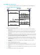
There are different types of Stelnet client software, such as PuTTY and OpenSSH. This example uses an Stelnet client that runs PuTTY version 0.58. To establish a connection to the Stelnet server: a. Launch PuTTY.exe to enter the interface shown in Figure 26. b. In the Host Name (or IP address) field, enter the IP address 192.168.1.40 of the Stelnet server. Figure 26 Specifying the host name (or IP address) c. Click Open to connect to the server.
Publickey authentication enabled Stelnet server configuration example Network requirements As shown in Figure 27, you can log in to the switch through the Stelnet client (SSH2) that runs on the host and are assigned the user role network-admin for configuration management. The switch acts as the Stelnet server and uses publickey authentication and the RSA public key algorithm. Figure 27 Network diagram Stelnet client 192.168.1.56/24 Stelnet server Vlan-int2 192.168.1.
b. Continuously move the mouse and do not place the mouse over the green progress bar shown in Figure 29. Otherwise, the progress bar stops moving and the key pair generating progress stops. Figure 29 Generating process c. After the key pair is generated, click Save public key, enter a file name (key.pub in this example), and click Save.
Figure 30 Saving a key pair on the client d. Click Save private key to save the private key. A confirmation dialog box appears. e. Click Yes, enter a file name (private.ppk in this example), and click Save. f. Transmit the public key file to the server through FTP or TFTP. (Details not shown.) 2. Configure the Stelnet server: # Generate the RSA key pairs. system-view [Switch] public-key local create rsa The range of public key size is (512 ~ 2048).
Generating Keys... .++++++++++++++++++++++++++++++++++++++++++++++++++* ........+......+.....+......................................+ ...+.................+..........+...+ Create the key pair successfully. # Enable the SSH server function. [Switch] ssh server enable # Assign an IP address to VLAN-interface 2. The Stelnet client uses this address as the destination for SSH connection. [Switch] interface vlan-interface 2 [Switch-Vlan-interface2] ip address 192.168.1.40 255.255.255.
Figure 31 Specifying the host name (or IP address) c. Select Connection > SSH from the navigation tree. The window shown in Figure 32 appears. d. Specify the Preferred SSH protocol version as 2.
e. Select Connection > SSH > Auth from the navigation tree. The window shown in Figure 33 appears. f. Click Browse… to bring up the file selection window, navigate to the private key file (private.ppk in this example), and click OK. Figure 33 Specifying the private key file g. Click Open to connect to the server. If the connection is successfully established, the system asks you to enter the username. After entering the username (client002), you can enter the CLI of the server.
Configuration procedure 1. Configure the Stelnet server: # Generate the RSA key pairs. system-view [SwitchB] public-key local create rsa The range of public key size is (512 ~ 2048). If the key modulus is greater than 512, it will take a few minutes. Press CTRL+C to abort. Input the modulus length [default = 1024]: Generating Keys... ........................++++++ ...................++++++ ..++++++++ ............++++++++ Create the key pair successfully. # Generate a DSA key pair.
[SwitchB] ssh user client001 service-type stelnet authentication-type password 2. Establish a connection to the Stelnet server 192.168.1.40: # Assign an IP address to VLAN-interface 2. system-view [SwitchA] interface vlan-interface 2 [SwitchA-Vlan-interface2] ip address 192.168.1.56 255.255.255.0 [SwitchA-Vlan-interface2] quit [SwitchA] quit Before establishing a connection to the server, you can configure the server's host public key on the client to authenticate the server.
[SwitchA-pkey-public-key-key1]485348 [SwitchA-pkey-public-key-key1] peer-public-key end [SwitchA] quit # Establish an SSH connection to the server 192.168.1.40 and specify the host public key of the server. ssh2 192.168.1.40 publickey key1 Username: client001 client001@192.168.1.40's password: After you enter the correct password, you successfully log in to Switch B.
[SwitchA] public-key local create dsa The range of public key size is (512 ~ 2048). If the key modulus is greater than 512, it will take a few minutes. Press CTRL+C to abort. Input the modulus length [default = 1024]: Generating Keys... .++++++++++++++++++++++++++++++++++++++++++++++++++* ........+......+.....+......................................+ ...+.................+..........+...+ Create the key pair successfully. # Export the DSA host public key to file key.pub.
[SwitchB] line vty 0 63 [SwitchB-line-vty0-63] authentication-mode scheme [SwitchB-line-vty0-63] quit # Import the peer public key from the file key.pub, and name it switchkey. [SwitchB] public-key peer switchkey import sshkey key.pub # Create an SSH user client002 with the authentication method publickey, and assign the public key switchkey to the user.
Configuration procedure 1. Configure the SFTP server: # Generate the RSA key pairs. system-view [Switch] public-key local create rsa The range of public key size is (512 ~ 2048). If the key modulus is greater than 512, it will take a few minutes. Press CTRL+C to abort. Input the modulus length [default = 1024]: Generating Keys... ........................++++++ ...................++++++ ..++++++++ ............++++++++ Create the key pair successfully. # Generate a DSA key pair.
The device supports different types of SFTP client software. This example uses an SFTP client that runs PSFTP of PuTTy version 0.58. NOTE: PSFTP supports only password authentication. To establish a connection to the SFTP server: a. Run the psftp.exe to launch the client interface shown in Figure 37, and enter the following command: open 192.168.1.45 b. Enter username client002 and password aabbcc as prompted to log in to the SFTP server.
Configuration procedure In the server configuration, the client's host public key is required. Use the client software to generate the RSA key pairs on the client before configuring the SFTP server. 1. Configure the SFTP client: # Assign an IP address to VLAN-interface 2. system-view [SwitchA] interface vlan-interface 2 [SwitchA-Vlan-interface2] ip address 192.168.0.2 255.255.255.0 [SwitchA-Vlan-interface2] quit # Generate the RSA key pairs.
.++++++++++++++++++++++++++++++++++++++++++++++++++* ........+......+.....+......................................+ ...+.................+..........+...+ Create the key pair successfully. # Enable the SFTP server function. [SwitchB] sftp server enable # Assign an IP address to VLAN-interface 2. The SSH client uses this address as the destination for SSH connection. [SwitchB] interface vlan-interface 2 [SwitchB-Vlan-interface2] ip address 192.168.0.1 255.255.255.
-rwxrwxrwx 1 noone nogroup 283 Aug 24 07:39 pubkey drwxrwxrwx 1 noone nogroup 0 Sep 01 06:22 new -rwxrwxrwx 1 noone nogroup 225 Sep 01 06:55 pub # Add a directory named new1 and verify the result. sftp> mkdir new1 sftp> dir -l -rwxrwxrwx 1 noone nogroup 1759 Aug 23 06:52 config.
• Do not generate a DSA key pair on the SCP server. Only RSA key pairs are supported. SCP file transfer with password authentication Network requirements As shown in Figure 39, Switch A acts as the SCP client, and Switch B acts as the SCP server. A user can securely transfer files with Switch B through Switch A. Switch B uses the password authentication method and the client's username and password are saved on Switch B. Figure 39 Network diagram Configuration procedure 1.
[SwitchB-Vlan-interface2] quit # Create a local device management user named client001 with the plaintext password aabbcc and service type ssh. [SwitchB] local-user client001 class manage [SwitchB-luser-manage-client001] password simple aabbcc [SwitchB-luser-manage-client001] service-type ssh [SwitchB-luser-manage-client001] quit # Create an SSH user client001 with service type scp and authentication method password. (If an SSH user is not created, password authentication is used by default.
Configuring IP source guard Overview IP source guard is a security feature. It is usually configured on a user access interface to help prevent spoofing attacks, in which an attacker uses, for example, the IP address of a valid host, to access the network. NOTE: The IP source guard function is available on Layer 2 and Layer 3 Ethernet interfaces and VLAN interfaces. The term "interface" in this chapter collectively refers to these types of interfaces.
Static IP source guard binding entries Static IP source guard binding entries are configured manually. They are suitable for scenarios where few hosts exist on a LAN and their IP addresses are manually configured. For example, you can configure a static IP source guard binding entry on an interface that connects to a server, allowing the interface to receive packets only from the server.
Configuring the IPv4 source guard function Enabling IPv4 source guard on an interface You must first enable the IPv4 source guard function on an interface before the interface can provide the following functions: • Obtain dynamic IPv4 source guard binding entries. • Use static and dynamic IPv4 source guard binding entries to filter packets or help other modules to provide security services. All the fields in a static IPv4 source guard binding entry are used by IP source guard to filter packets.
Configuring a static IPv4 source guard binding entry Static IPv4 source guard binding entries include global static IPv4 source entries and interface-specific static IPv4 source guard binding entries. A global static IPv4 source guard binding entry defines both the source IP address and source MAC address of packets that can be forwarded, and it takes effect on all interfaces. Static IPv4 source guard binding entries on an interface take priority over the global static IPv4 source guard binding entries.
Task Command Display IPv4 source guard binding entries (in standalone mode). display ip source binding [ static | [ dhcp-relay | dhcp-server | dhcp-snooping ] ] [ ip-address ip-address ] [ mac-address mac-address ] [ vlan vlan-id ] [ interface interface-type interface-number ] [ slot slot-number ] Display IPv4 source guard binding entries (in IRF mode).
# On FortyGigE 1/0/2, configure a static IPv4 source guard binding entry for Host C. [SwitchA-FortyGigE1/0/2] ip source binding ip-address 192.168.0.3 mac-address 0001-0203-0405 [SwitchA-FortyGigE1/0/2] quit # Enable IPv4 source guard on FortyGigE 1/0/1. [SwitchA] interface fortygige 1/0/1 [SwitchA-FortyGigE1/0/1] ip verify source ip-address mac-address # On FortyGigE 1/0/1, configure a static IPv4 source guard binding entry for Host A. [SwitchA-FortyGigE1/0/1] ip source binding ip-address 192.168.0.
Dynamic IPv4 source guard using DHCP snooping configuration example Network requirements As shown in Figure 42, the host (the DHCP client) is connected to FortyGigE 1/0/1 of the device, and obtains an IP address from the DHCP server. The DHCP server is connected to FortyGigE 1/0/2 of the device. Enable DHCP snooping on the device, so that the host can obtain an IPv4 address from the valid DHCP server and the IPv4 address and the MAC address of the host can be recorded in a DHCP snooping entry.
IP Address MAC Address 192.168.0.1 0001-0203-0406 FGE1/0/1 Interface VLAN Type 1 DHCP snooping The output shows that IP source guard has generated a dynamic IPv4 source guard binding entry on FortyGigE 1/0/1 based on the DHCP snooping entry. Dynamic IPv4 source guard using DHCP relay configuration example Network requirements As shown in Figure 43, the host and the DHCP server are connected to the switch through interfaces VLAN-interface 100 and VLAN-interface 200 respectively.
[Switch] display ip source binding dhcp-relay Total entries found: 1 IP Address MAC Address 192.168.0.
Configuring ARP attack protection ARP attacks and viruses are threatening LAN security. This chapter describes multiple features used to detect and prevent ARP attacks. Although ARP is easy to implement, it provides no security mechanism and is vulnerable to network attacks. An attacker can exploit ARP vulnerabilities to attack network devices in the following ways: • Acts as a trusted user or gateway to send ARP packets so the receiving devices obtain incorrect ARP entries.
Step Command Remarks 2. Enable ARP source suppression. arp source-suppression enable By default, ARP source suppression is disabled. 3. Set the maximum number of unresolvable packets that the device can receive from a host within 5 seconds. arp source-suppression limit limit-value By default, the maximum number is 10. Displaying and maintaining unresolvable IP attack protection Execute display commands in any view. Task Command Display ARP source suppression configuration information.
system-view [Device] arp source-suppression enable # Set the maximum number of unresolvable packets that can be received from a host in 5 seconds to 100. [Device] arp source-suppression limit 100 Configuring ARP detection ARP detection enables access devices to block ARP packets from unauthorized clients to prevent user spoofing and gateway spoofing attacks. ARP detection does not check ARP packets received from ARP trusted ports.
Step (Optional.) Configure the interface as a trusted interface excluded from ARP detection. 6. Command Remarks arp detection trust By default, an interface is untrusted. Configuring ARP packet validity check Enable validity check for ARP packets received on untrusted ports and specify the following objects to be checked: • src-mac—Checks whether the sender MAC address in the message body is identical to the source MAC address in the Ethernet header. If they are identical, the packet is forwarded.
If the packets are ARP replies, they are forwarded according to their destination MAC address. If no match is found in the MAC address table, they are forwarded through the trusted interface. • Configured user validity check before you configure ARP restricted forwarding. To enable ARP restricted forwarding: Step Command Remarks 1. Enter system view. system-view N/A 2. Enter VLAN view. vlan vlan-id N/A 3. Enable ARP restricted forwarding.
Figure 45 Network diagram Configuration procedure 1. Add all interfaces on Switch B to VLAN 10, and specify the IP address of VLAN-interface 10 on Switch A. (Details not shown.) 2. Configure the DHCP server on Switch A, and configure DHCP address pool 0. system-view [SwitchA] dhcp enable [SwitchA] dhcp server ip-pool 0 [SwitchA-dhcp-pool-0] network 10.1.1.0 mask 255.255.255.0 3. Configure Host A (DHCP client) and Host B. (Details not shown.) 4. Configure Switch B: # Enable DHCP snooping.
[SwitchB] interface fortygige 1/0/2 [SwitchB-FortyGigE1/0/2] ip source binding ip-address 10.1.1.6 mac-address 0001-0203-0607 vlan 10 [SwitchB-FortyGigE1/0/2] quit # Enable ARP packet validity check by checking the MAC addresses and IP addresses of ARP packets.
Configuring uRPF Overview Unicast Reverse Path Forwarding (uRPF) protects a network against source address spoofing attacks, such as DoS and DDoS attacks. Attackers send packets with a forged source address to access a system that uses IP-based authentication, in the name of authorized users or even the administrator. Even if the attackers or other hosts cannot receive any response packets, the attacks are still disruptive to the attacked target.
Figure 47 uRPF work flow Checks the received packet Yes Broadcast source address? No Yes All-zero source address? Yes No Broadcast destination address? No No Discards the packet No Matching FIB entry found? Default route found? Yes Yes Yes Yes Loose uRPF? Loose uRPF? No No Yes Matching route is a direct route? Yes Receiving interface matches the output interface of the default route? No No Yes Source IP address matches an ARP entry? No Receiving interface matches the output inter
2. 3. 4. 5. 6. 7. uRPF checks whether the source address matches a FIB entry: { If yes, proceeds to step 3. { If no, proceeds to step 6. uRPF checks whether the check mode is loose: { If yes, proceeds to step 8. { If no, uRPF checks whether the matching route is a direct route: − If yes, proceeds to step 5. − If no, proceeds to step 4. uRPF checks whether the receiving interface matches the output interface of the matching FIB entry: { If yes, proceeds to step 8.
Network application Figure 48 Network diagram Configure strict uRPF check between an ISP network and a customer network, and loose uRPF check between ISPs. Configuring uRPF To enable uRPF globally: Step Command Remarks 1. Enter system view. system-view N/A 2. Enable uRPF globally. ip urpf { loose | strict } By default, uRPF is disabled. Displaying and maintaining uRPF Execute display commands in any view. Task Command Display uRPF configuration (in standalone mode).
uRPF configuration example Network requirements As shown in Figure 49, a client (Switch A) directly connects to an ISP switch (Switch B). Enable strict uRPF check on Switch A and Switch B to prevent source address spoofing attacks. Figure 49 Network diagram Configuration procedure 1. Enable strict uRPF check on Switch A. system-view [SwitchA] ip urpf strict 2. Enable strict uRPF check on Switch B.
Configuring FIPS Overview Federal Information Processing Standards (FIPS) was developed by the National Institute of Standard and Technology (NIST) of the United States. FIPS specifies the requirements for cryptographic modules. FIPS 140-2 defines four levels of security, named "Level 1" to "Level 4", from low to high. The device supports Level 2. Unless otherwise noted, in this document the term "FIPS" refers to FIPS 140-2.
{ save. { Other commands used for configuration preparation to enter FIPS mode. • If a device enters FIPS or non-FIPS mode through automatic reboot, the startup configuration file does not support configuration rollback. To support configuration rollback, you must execute the save command before making other configurations. • Do not use FIPS and non-FIPS devices to create an IRF fabric. • To enable FIPS mode for an IRF fabric, you must reboot the entire IRF fabric.
{ A username. { A password that complies with the password control policies as described in step 2 and step 3. { A user role of network-admin. { A service type of terminal. 5. Delete the FIPS-incompliant local user service types Telnet and FTP. 6. Enable FIPS mode. 7. Select the manual reboot method. 8. Save the configuration file and specify it as the startup configuration file. 9. Delete the startup configuration file in binary format (an .mdb file). 10. Reboot the device.
Exiting FIPS mode After you disable FIPS mode and reboot the device, the device operates in non-FIPS mode. The non-FIPS device does not have the security requirements of FIPS mode, and does not perform self-tests on cryptography modules. The system provides two methods to exit FIPS mode: automatic reboot and manual reboot. Automatic reboot Select the automatic reboot method. The system automatically creates a default non-FIPS configuration file named non-fips-startup.
the card where the self-test process exists reboots. If the conditional self-test fails, the system outputs self-test failure information. NOTE: If a self-test fails, contact HP Support. Power-up self-tests The power-up self-test, also called "known-answer test", examines the availability of FIPS-allowed cryptographic algorithms. A cryptographic algorithm is run on data for which the correct output is already known. The calculated output is compared with the known answer.
Step Command 1. Enter system view. system-view 2. Trigger a self-test. fips self-test Displaying and maintaining FIPS Execute the display command in any view. Task Command Display the FIPS mode state. display fips status FIPS configuration examples Entering FIPS mode through automatic reboot Network requirements Use the automatic reboot method to enter FIPS mode, and use a console port to log in to the device in FIPS mode.
First login or password reset. For security reason, you need to change your password. Please enter your password. old password: new password: confirm: Updating user information. Please wait ... ... … # Display the current FIPS mode state. display fips status FIPS mode is enabled. # Display the default configuration file. more fips-startup.
[Sysname-luser-manage-test] service-type terminal [Sysname-luser-manage-test] quit # Enable FIPS mode, and choose the manual reboot method to enter FIPS mode. [Sysname] fips mode enable FIPS mode change requires a device reboot. Continue? [Y/N]:y Reboot the device automatically? [Y/N]:n Change the configuration to meet FIPS mode requirements, save the configuration to the next-startup configuration file, and then reboot to enter FIPS mode.
Exiting FIPS mode through automatic reboot Networking requirements A user has logged in to the device in FIPS mode through a console port. Use the automatic reboot method to exit FIPS mode. Configuration procedure # Disable FIPS mode. [Sysname] undo fips mode enable FIPS mode change requires a device reboot. Continue? [Y/N]:y The system will create a new startup configuration file for non-FIPS mode and then reboot automatically. Continue? [Y/N]:y Waiting for reboot...
Validating file. Please wait... Saved the current configuration to mainboard device successfully. [Sysname] quit # Delete the startup configuration file in binary format. delete flash:/startup.mdb Delete flash:/startup.mdb?[Y/N]:y Deleting file flash:/startup.mdb...Done. # Reboot the device. reboot Verifying the configuration After the device reboots, enter the username test and password 12345zxcvb!@#$%ZXCVB to enter non-FIPS mode. Press ENTER to get started.
Support and other resources Contacting HP For worldwide technical support information, see the HP support website: http://www.hp.
Conventions This section describes the conventions used in this documentation set. Command conventions Convention Description Boldface Bold text represents commands and keywords that you enter literally as shown. Italic Italic text represents arguments that you replace with actual values. [] Square brackets enclose syntax choices (keywords or arguments) that are optional. { x | y | ... } Braces enclose a set of required syntax choices separated by vertical bars, from which you select one.
Network topology icons Represents a generic network device, such as a router, switch, or firewall. Represents a routing-capable device, such as a router or Layer 3 switch. Represents a generic switch, such as a Layer 2 or Layer 3 switch, or a router that supports Layer 2 forwarding and other Layer 2 features. Represents an access controller, a unified wired-WLAN module, or the switching engine on a unified wired-WLAN switch. Represents an access point.
Index RADIUS accounting server parameter specification, 21 Numerics 3DES RADIUS accounting-on feature configuration, 26 IPsec encryption algorithm, 72 RADIUS attributes, 11 A RADIUS authentication server specification, 21 AAA RADIUS implementation, 2 configuration, 1, 14 RADIUS max request transmission attempts, 23 device implementation, 9 RADIUS scheme configuration, 20 displaying, 38 RADIUS scheme creation, 20 displaying local users/local user groups, 19 FIPS compliance, 14 RADIUS security
user validity check, 154 IPsec ACL de-encapsulated packet check, 81 user/packet validity check, 156 IPsec ACL rule keywords, 74 IPsec ACL-based implementation, 72, 73 ARP detection IPsec ACL-based tunnel establishment, 73 IPsec configuration, 74 security IP source guard static binding entry, 144 associating IPsec mirror image ACLs, 75 IPsec non-mirror image ACLs, 75 IPsec SA, 71 attribute security SSH management parameters, 115 security AAA HWTACACS scheme configuration, 28 address security uRPF
security SSH methods, 110 security SSH SCP file transfer with password authentication, 141 security AAA command accounting method, 10 security AAA command authorization method, 10 communication security SSH server configuration, 111 security peer public key entry, 64 security SSH SFTP client publickey authentication, 137 complexity checking (password control), 49 security SSH SFTP server password authentication, 135 conditional self-test, 168 security SSH Stelnet client password authentication confi
security AAA RADIUS security policy server IP address, 27 security SSH Stelnet client password authentication, 130 security AAA RADIUS server SSH user authentication+authorization, 42 security SSH Stelnet client publickey authentication, 133 security AAA scheme, 15 security SSH Stelnet server password authentication, 122 security AAA SSH user local authentication+HWTACACS authorization+RADIUS accounting, 40 security SSH Stelnet server publickey authentication, 125 security AAA user group attributes,
security SSH Stelnet client configuration, 116 security AAA ISP domain attribute configuration, 34 security SSH Stelnet server connection establishment, 117 security AAA ISP domain authentication methods, 35 security Stelnet client user line configuration, 113 security AAA ISP domain authorization methods, 36 security super password control parameters, 55 Don't Fragment bit.
mode configuration, 165 encrypting IPsec, 72 mode entry, 165 IPsec configuration, 69, 85 mode entry (automatic reboot), 169 IPsec encryption algorithm (3DES), 72 mode entry (manual reboot), 170 IPsec encryption algorithm (AES), 72 mode exit, 167 IPsec encryption algorithm (DES), 72 mode exit (automatic reboot), 172 IPsec IKE-based tunnel for IPv4 packets configuration, 88 mode exit (manual reboot), 172 mode system changes, 166 IPsec tunnel for IPv4 packets configuration, 85 security peer public
IKE, 91, See also ISAKMP G configuration, 91, 93 generating configuration (main mode/pre-shared key authentication), 101 security SSH local DSA key pair, 111 security SSH local RSA key pair, 111 DH algorithm, 92 H displaying, 101 history DPD configuration, 98 security password history, 50 global identity information configuration, 97 HP identity authentication, 92 security AAA RADIUS HP proprietary attributes, 13 invalid SPI recovery, 99 IPsec IKE SNMP notification, 100 HW Terminal Access Co
security ARP unresolvable IP attack protection (source suppression), 152 IKE invalid SPI recovery, 99 IKE keepalive function configuration, 98 security ARP unresolvable IP attack protection display, 153 IKE keychain configuration, 96 IKE NAT keepalive function configuration, 98 security uRPF configuration, 159, 163 IKE negotiation, 91 uRPF configuration, 162 IKE negotiation failure troubleshooting (invalid identity info), 106 IP addressing security AAA HWTACACS outgoing packet source IP address, 31
configuration, 143, 144, 145, 147 IPsec configuration, 69, 85 displaying, 146 IPsec IKE-based tunnel for IPv4 packets configuration, 88 dynamic binding entry, 144 dynamic configuration with DHCP relay, 150 dynamic configuration with DHCP snooping, 149 IPsec tunnel for IPv4 packets configuration, 85 local security AAA local accounting method, 10 enable on interface, 145 security AAA local authentication, 10 maintaining, 146 security AAA local authentication configuration, 14 static binding entry, 1
security ARP detection, 156 IPsec packet DF bit, 83 security IP source guard, 146 IPsec packet logging enable, 83 security IPv4 source guard, 146 IPsec policy application to interface, 80 security password control, 55 IPsec policy configuration, 76 IPsec policy configuration (IKE-based), 78 managing IPsec QoS pre-classify enable, 82 security public keys, 59, 64 IPsec SNMP notification, 84 message IPsec source interface policy bind, 82 security ARP attack protection configuration, 152 IPsec tr
security SSH management parameters, 115 security ARP attack protection configuration, 152 security SSH SCP client device configuration, 121 security FIPS configuration, 164, 169 security SSH server configuration, 111 security FIPS mode entry (manual reboot), 170 security FIPS mode entry (automatic reboot), 169 security SSH server function enable, 112 security FIPS mode exit (automatic reboot), 172 security SSH SFTP client device configuration, 118 security IP source guard configuration, 143, 144
packet security SSH password authentication, 110 IPsec ACL de-encapsulated packet check, 81 security SSH password-publickey authentication, 110 IPsec anti-replay configuration, 81 security SSH SCP file transfer with password authentication, 141 IPsec implementation, 72 IPsec packet DF bit configuration, 83 security SSH SFTP server password authentication, 135 IPsec packet logging enable, 83 IPsec QoS pre-classify enable, 82 security SSH Stelnet client password authentication, 130 security AAA HWTA
I XE, 78 configuring security AAA HWTACACS schemes, 28 IPsec application to interface, 80 configuring security AAA HWTACACS server SSH user, 39 IPsec configuration, 76 configuring security AAA ISP domain accounting methods, 37 IPsec QoS pre-classify enable, 82 IPsec source interface policy bind, 82 configuring security AAA ISP domain attributes, 34 IPsec transform set configuration, 75 security AAA RADIUS security policy server IP address configuration, 27 configuring security AAA ISP domain author
configuring security password control, 51, 56 displaying security ARP detection, 156 configuring security public peer key, 63 displaying security ARP unresolvable IP attack protection, 153 configuring security SSH client host public key, 113 displaying security FIPS, 169 configuring security SSH device as server, 111 displaying security host public key, 62, 62 configuring security SSH device as SFTP client, 118 displaying security IP source guard, 146 configuring security SSH device as Stelnet cli
maintaining security ARP detection, 156 specifying security SSH SFTP client source IP address/interface, 118 maintaining security IP source guard, 146 specifying security SSH Stelnet client source IP address or interface, 117 maintaining security IPv4 source guard, 146 maintaining security password control, 55 terminating security SSH SFTP server connection, 121 saving security host public key to file, 62 setting security AAA HWTACACS timer, 32 troubleshooting IPsec IKE, 104 setting security AAA HWT
security policy server IP address configuration, 27 security SSH SFTP client publickey authentication, 137 server quiet timer, 25 security SSH Stelnet client publickey authentication, 133 server response timeout timer, 25 server status, 23 security SSH Stelnet server publickey authentication, 125 session-control feature configuration, 38 shared keys specification, 22 security SSH user configuration, 114 traffic statistics units, 22 public key management troubleshooting, 45 FIPS compliance, 59 tr
ARP attack protection (unresolvable IP attack), 152 IPsec ACL rule keywords, 74 ARP detection configuration, 154 S ARP packet validity check, 155 SA ARP restricted forwarding, 155 IKE SA max number set, 100 ARP source suppression, 152 IPsec transform set configuration, 75 ARP unresolvable IP attack protection, 153 saving ARP user validity check configuration, 154 security host public key to file, 62 ARP user/packet validity check, 156 SCP association.
IPsec IKE global identity information configuration, 97 maintaining password control, 55 IPsec IKE invalid SPI recovery, 99, 99 password control enable, 51 password control configuration, 48, 51, 56 IPsec IKE keepalive function configuration, 98 password control global parameters, 52 IPsec IKE keychain configuration, 96 password control local user parameters, 54 IPsec IKE mechanism, 92 password control user group parameters, 53 IPsec IKE NAT keepalive function configuration, 98 password event lo
SSH Stelnet client password authentication, 130 security password control local user parameters, 54 SSH Stelnet client publickey authentication, 133 security password control user group parameters, 53 SSH Stelnet client source IP address/interface, 117 security SSH management parameters, 115 SSH Stelnet configuration, 122 SSH Stelnet server connection establishment, 117 security super password control parameters, 55 SFTP client device configuration, 118 SSH Stelnet server password authentication, 12
security SSH Stelnet client source IP address or interface, 117 server configuration, 111 server function enable, 112 SPI Stelnet, 109 IPsec IKE invalid SPI recovery, 99 Stelnet client device configuration, 116 spoofing Stelnet client password authentication, 130 security uRPF configuration, 159, 163 Stelnet client publickey authentication, 133 uRPF configuration, 162 Stelnet client source IP address/interface, 117 SSH Stelnet client user line configuration, 113 authentication methods, 110 Ste
security SSH Stelnet client device configuration, 116 transporting security SSH Stelnet client password authentication, 130 triggered self-test, 168 security SSH Stelnet client publickey authentication, 133 IPsec encapsulation transport mode, 70 troubleshooting IPsec IKE, 104 IPsec IKE negotiation failure (invalid identity info), 106 security SSH Stelnet client source IP address/interface, 117 IPsec IKE negotiation failure (no IKE proposal or IKE keychain referenced correctly), 105 security SSH Stel
security IPv4 source guard dynamic configuration with DHCP relay, 150 IP source guard configuration, 147 security IP source guard configuration, 143, 144 security IPv4 source guard dynamic configuration with DHCP snooping, 149 security IPv4 source guard dynamic configuration with DHCP relay, 150 security IPv4 source guard dynamic configuration with DHCP snooping, 149 security IPv4 source guard static configuration, 147 security IPv4 source guard static configuration, 147 W working with security SSH SFTP