HP GbE2c Ethernet Blade Switch for c-Class BladeSystem User Guide May 2006 (First Edition) Part Number 418116-001
© Copyright 2006 Hewlett-Packard Development Company, L.P. The information contained herein is subject to change without notice. The only warranties for HP products and services are set forth in the express warranty statements accompanying such products and services. Nothing herein should be construed as constituting an additional warranty. HP shall not be liable for technical or editorial errors or omissions contained herein.
Contents Introduction .................................................................................................................................. 6 Overview ................................................................................................................................................. 6 Additional references................................................................................................................................. 6 Features ......................................
Replacing and upgrading the switch ............................................................................................. 22 Replacing an existing switch ..................................................................................................................... 22 Regulatory compliance notices ..................................................................................................... 24 Class A equipment ............................................................................
Cannot connect to the switch remotely using the Web interface ..................................................................... 50 Cannot enable a port in multiple VLANs while configuring VLANS................................................................. 51 The switch does not let the user enable two adjacent ports into two different VLANs while assigning the ports to VLANs ...............................................................................................................................
Introduction In this section Overview ................................................................................................................................................ 6 Additional references................................................................................................................................ 6 Features ..................................................................................................................................................
• Fully supported on the HP c-Class BladeSystem server blade enclosure and infrastructure compatible with any combination of HP c-Class BladeSystem server blades • Ability to replace an existing switch without having to power down the server blades or the server blade enclosure • Pre-configured for immediate use with the HP c-Class BladeSystem server blade enclosure • System security including SSH, SCP, 255 port-based IEEE 802.
• Port Fast Forwarding that allows a port that participates in Spanning Tree to bypass the Listening and Learning states and enter directly into the Forwarding state. • Allows secure browser access (HTTPS) to management functions Switch redundancy In a dual switch configuration, the switches offer several redundancy and failover features. With these features, the network configuration is designed to allow for continued network access to each server blade in case of a component or link failure.
• Any switch port can be used to perform switch management and PXE.
Redundant paths to server bays In a dual switch configuration, redundant Ethernet signals from each blade server are routed through the enclosure backplane to separate switches within the enclosure. This configuration provides redundant paths to each server bay. Redundant Ethernet signals from each blade server are routed through the enclosure backplane to separate switches within the enclosure. However, specific switch port to server mapping varies depending on which type of server blade is installed.
In addition, the switch provides a spanning tree domain per VLAN. The switch is compatible with Cisco® PVST+ and Cisco PVST, when the other device is configured as untagged or configured to use 802.1q tagging. Sixteen spanning tree domains are supported per switch. NOTE: STP 16 is reserved for future functionality. The switch also provides IEEE 802.1s-based MSTP and IEEE 802.1w-based RSTP. SNMP The switch is configured and monitored remotely from an SNMP-based network management station.
configurable from the browser-based interface, but because the connection is based on an IP address for these interfaces, users will have to reconnect with the newly assigned IP address. NTP The switch maintains the current date and time. This information displays on the management interfaces and is used to record the date and time of switch events. Current date and time information are manually set on the switch or are obtained through NTP.
• Only standard ASCII inbound login authentication. PAP, CHAP, or ARAP login methods are not supported. One-time password authentication is also not supported. • Authorization privilege levels of only 0, 3, and 6. These map to management levels of user, oper, and admin, respectively. • The accounting attributes of protocol, start_time, stop_time, and elapsed_time. For BBI users, accounting stop records are only sent if the user presses the QUIT button.
through a procedure called auto-negotiation. Auto-negotiation involves probing the capability of the network using low-level signaling techniques to select compatible Ethernet speeds. Auto-negotiation was originally developed to make the migration from traditional Ethernet to Fast Ethernet products easier. Redundant images in firmware The switch stores up to two different software images, called image1 and image2, as well as boot software, called boot.
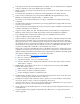
Item Description 4 DB-9 management serial port 5 RJ-45 ports 20 - 24 Description CAUTION: Pressing the Reset button while the Health LED is green resets the switch.
Installing the switch In this section Planning the switch configuration ............................................................................................................. 16 Installing the switch ................................................................................................................................ 18 Accessing the switch...............................................................................................................................
• SNMP settings • User name and password settings • Default access to various management interfaces • NTP settings IMPORTANT: See "Runtime switching software default settings (on page 28)" for a complete list of default configuration settings.
User account Description and tasks performed Operator The operator manages all functions of the switch. The operator can reset ports or the entire switch. Password By default, the operator account is disabled and has no password. Administrator The super user administrator has complete access to all menus, information, and configuration commands on the switch, including the ability to change both the user and administrator passwords.
Installing the switch CAUTION: Do not cable the switch until after configuration. IMPORTANT: Make sure that the server NIC configuration matches the switch bay selected. NOTE: When installing two switches, there are two switch interconnect ports between adjacent I/O bays. These ports (17 and 18) are disabled by default. The ports must be manually enabled to use. To install the switch: 1. Remove the blank. 2. Install the switch.
To access the switch remotely: 1. Assign an IP address. By default, the switch is set up to obtain its IP address from a BOOTP server existing on the attached network. 2. From the BOOTP server, use the switch MAC address to obtain the switch IP address. 3. From a computer connected to the same network, use the IP address to access the switch using a Web browser or telnet application, which enables access to the switch BBI or CLI. The switch logon prompt appears.
See "SNMP MIBs support (on page 42)" for more information on the SNMP agents. This section also describes how to use the MIBs to configure and monitor the switch using a generic SNMP manager, such as HP OpenView Network Node Manager or HP Systems Insight Manager. Cabling the switch CAUTION: Do not cable the switch until after configuration. To connect the switch to the network: 1. Connect the network cables to the switch. 2. Gather the network cables for the right side of the rack. 3.
Replacing and upgrading the switch In this section Replacing an existing switch.................................................................................................................... 22 Replacing an existing switch CAUTION: Removing the switch from a powered enclosure results in the loss of network communications between the server blade network ports that are connected through this switch and the segment of network infrastructure those ports need to communicate.
5. If the configuration file was saved to a TFTP server, download the configuration. For more information on downloading a configuration file, see the HP GbE2c Ethernet Blade Switch for cClass BladeSystem Command Reference Guide.
Regulatory compliance notices In this section Class A equipment ................................................................................................................................. 24 Modifications......................................................................................................................................... 24 Cables ..................................................................................................................................................
European Union regulatory notice This product complies with the following EU Directives: • Low Voltage Directive 73/23/EEC • EMC Directive 89/336/EEC Compliance with these directives implies conformity to applicable harmonized European standards (European Norms) which are listed on the EU Declaration of Conformity issued by Hewlett-Packard for this product or product family.
Korean class A notice Laser compliance This product may be provided with an optical storage device (that is, CD or DVD drive) and/or fiber optic transceiver. Each of these devices contains a laser that is classified as a Class 1 Laser Product in accordance with US FDA regulations and the IEC 60825-1. The product does not emit hazardous laser radiation. Each laser product complies with 21 CFR 1040.10 and 1040.11 except for deviations pursuant to Laser Notice No.
Technical specifications In this section General specifications ............................................................................................................................ 27 Runtime switching software default settings................................................................................................ 28 Physical and environmental specifications ................................................................................................. 35 Performance specifications .......
Category Specification Number of ports per switch: 16 x 1000-Mb/s ports dedicated to server blade for switch communications 2 x 1000-Mb/s ports dedicated to communications between switches that are inserted in 1 and 2, 3 and 4, 5 and 6, or 7 and 8 5 x 10Base-T/100Base-TX/1000Base-T RJ-45 ports 1 x serial RS-232 DB-9 rear panel management serial port Runtime switching software default settings General default settings Setting Value Notice None Banner None User names and passwords User names and pa
Setting Value Backpressure Disabled Port state Enabled Port speed/duplex Auto Flow control Receive & transmit STP STG 1—Enabled with default VLAN (VID=1) Port 1-16 (server ports) STP—Disabled at port level STG 2-16—Disabled Bridge Max Age 20 seconds Bridge Hello Time 2 seconds Bridge Forward Delay 15 seconds Bridge Priority 32768 MAC Address Aging Time 300 seconds Port Priority 128 Path Cost 4 Static VLAN Entry Default VLAN (VID = 1) Port VID 1 for all ports Port Trunking Trun
Setting Value SNMP Authentication Traps Disabled SNMP Link Up/Down Traps Enabled Security IP Network/Mask 0.0.0.0 / 0.0.0.0 TFTP Server IP Address 0.0.0.
Setting Value Log • console—Enabled • system—Enabled • mgmt—Enabled • cli—Enabled • stp—Enabled • vlan—Enabled • ssh—Enabled • ntp—Enabled • ip—Enabled • web—Enabled RSA Server Key Autogen Interval 0 RSA Server Key Autogen Disabled SSH Server On SCP-only Administrator Password admin SSH Server Port 22 SCP Apply and Save Disabled RADIUS Server Off RADIUS Secret None Primary RADIUS Server 0.0.0.0 Secondary RADIUS Server 0.0.0.
Setting Value MSTP Edge Port Enabled: ports 1-16 TACACS+ Service Off TACACS+ Primary Secret None TACACS+ Secondary Secret None Primary TACACS+ Server 0.0.0.0 Secondary TACACS+ Server 0.0.0.
Setting Value RMON Event Group Number None RMON Event Description None RMON Event Type None RMON Alarm Group Number None RMON Alarm MIB to Monitor None RMON Alarm Interval 1800 RMON Alarm Sample Type abs RMON Alarm Type either RMON Alarm Rising Threshold 0 RMON Alarm Falling Threshold 0 RMON Alarm Rising Event 0 Index RMON Alarm Falling Event 0 Index RMON Alarm Owner Null IP Forwarding Disabled Configurable User Name admpw admin Configurable User Name opw Disabled Configurable
Setting Value MCAST/BCAST/UCAST off SNMPv3 - SNMP access read/write enabled SNMPv3 - v1v2 access Enabled SNMPv3 - adminmd5 authentication = md5, privacy = des SNMPv3 - adminsha authentication = sha, privacy = des SNMPv3 - v1v2only authentication = none, privacy = none SNMPv3 - admingrp level=authPriv, users=adminmd5, adminsha, rview, wview, nview=iso SNMPv3 - v1v2grp level=noAuthNoPriv, users=v1v2only, rview, wview=iso, nview=v1v2only SNMPv3 - iso subtree = 1, included SNMPv3 - v1v2only
Port type Port number Port name STP Trunk group Server 11 Downlink11 Disabled Server 12 Downlink12 Disabled Server 13 Downlink13 Disabled Server 14 Downlink14 Disabled Server 15 Downlink15 Disabled Server 16 Downlink16 Disabled X-Connect 17 XConnect1 Enabled 1 X-Connect 18 XConnect1 Enabled 1 Reserved for future use 19 Uplink 20 Uplink1 Enabled Uplink 21 Uplink2 Enabled Uplink 22 Uplink3 Enabled Uplink 23 Uplink4 Enabled Uplink 24 Uplink5 Enabled
Category Specification MAC address table size 8 KB per switch Packet forwarding rate 1,488,095 packets per second with 64 byte packets per port (for 1000 Mb/s) Maximum external 5 X 1 GB port = 5 X 1,488,095 = 7,440,475 pps per port packet switch forwarding rate Best downlink external port packet forwarding rate ratio 16 : 5 Interswitch xconnects across enclosure backplane 2 X 1 GB ports bundled in Port Trunk of 2 GB size MAC address learning Automatic update Forwarding table age time Maximum ag
Performing a serial download In this section Introduction ........................................................................................................................................... 37 Serial upgrade of boot code firmware image procedure ............................................................................. 37 Serial upgrade of operating system firmware procedure .............................................................................
4. Hold down the Shift key and press the D key repeatedly during the Memory Test, until this message appears: NOTE: To perform serial downloads at 57600 baud rate, press the Shift-F keys. To perform serial downloads at 115200 baud rate, press the Shift-D keys. 5. After the message in Step 4 appears, reconfigure the terminal emulation console using these parameters. Parameter Value Baud rate 115200 Data bits 8 Parity None Stop bits 1 Flow control None 6.
CAUTION: Do not power off the switch until the message: "Change your baud rate to 9600 bps and power cycle the switch," is displayed, otherwise, the switch will be inoperable. 10. Change the baud rate to 9600 and power off the switch, wait for a few seconds, and power on the switch. The switch boots with the new version of the boot code image that was just downloaded.
5. After the message in Step 4 appears, reconfigure the terminal emulation console using these parameters. Parameter Value Baud rate 115200 Data bits 8 Parity None Stop bits 1 Flow control None 6. Press the Enter key several times on the PC that is connected to the console port of the switch. When the console port is successfully communicating with the PC, indicating readiness for image transfer, continuous C's appear: 7.
Depending on the selection, 1 or 2, the system updates image1 or image2 on the flash and a message with a progress indicator displays as shown below. If selecting n, the system aborts the update procedure and prompts to reset the baud rate and power cycle the switch. -or- -or- 11. Change the baud rate to 9600 and power off the switch. Wait for a few seconds, and power on the switch. During bootup the switch the following prompt appears: To use the other operating system image, press the Ctrl-o keys.
SNMP MIBs support In this section MIB overview......................................................................................................................................... 42 SNMP Manager software........................................................................................................................ 42 Supported MIBs ..................................................................................................................................... 43 Supported traps ............
Supported MIBs The SNMP agent for the switch supports these MIBs: • bt2Network.mib • bt2Physical.mib • bt2Switch.mib • bt2trap.mib • cpqhost.mib • cpqsinfo.mib • cpqrack.mib • hpswitchpl.mib • rfc1213.mib • rfc1493.mib • rfc1573.mib • rfc1643.mib • rfc1757.mib • rfc1907.mib • rfc2037.mib • rfc2571.mib • rfc2572.mib • rfc2573.mib • rfc2574.mib • rfc2575.mib • rfc2576.mib Supported traps The switch SNMP agent supports these traps: • bt2trap.
• • • • bt2SwUfdfoGlobalEna • bt2SwUfdfoGlobalDis • bt2SwUfdfoLtDAutoEna • bt2SwUfdfoLtDAutoDis rfc1215.mib traps • coldStart • warmStart • linkDown • linkUp • authenticationFailure • egpNeighborLoss rfc1493.mib traps • newRoot • topologyChange rfc1757.
Electrostatic discharge In this section Preventing electrostatic discharge............................................................................................................. 45 Grounding methods to prevent electrostatic discharge ................................................................................ 45 Preventing electrostatic discharge To prevent damaging the system, be aware of the precautions you need to follow when setting up the system or handling parts.
RJ-45 pin specification In this section Standard RJ-45 receptacle/connector ....................................................................................................... 46 Standard RJ-45 receptacle/connector When connecting the switch to a switch, bridge, or hub, an Ethernet cable is necessary.
Troubleshooting In this section Forgotten administrator user name and password that was configured on the switch ...................................... 47 Health LED on the switch is not on ............................................................................................................ 47 Health LED on the switch stays amber for more than 30 seconds and switch does not boot .............................
• The server blade enclosure is not powered up. Be sure that the server blade enclosure is powered up and all the power connections are intact. • There is a faulty LED. Check the console to see if the switch is booted. • The switch fuse is blown. Send for repair. Health LED on the switch stays amber for more than 30 seconds and switch does not boot Action: The Standby Mode Timeout function is malfunctioning. Force the switch to reboot by pressing the Reset button.
The switch fails to get its IP settings from the BOOTP server, even though by default it is configured for BOOTP Action: • The switch is not connected properly to the network. Check the cable and connections and be sure that there is network connectivity between the switch and the BOOTP server. • The BOOTP server is not available on the network or VLAN that is attached to the switch management port. Be sure that the BOOTP server is present on the network or VLAN attached to the switch.
• The switch IP address is not configured or correct. • From the serial console interface, be sure that the switch IP address is configured and valid on the network. • Use the correct IP address to establish the SSH connection with the switch. • The setting allowing access to the switch using the SSH interface is disabled. • From the serial console interface, be sure that the SSH interface is enabled and all the settings are configured correctly.
• The management network address/mask (if used) does not contain the IP address of the management station. From the serial console interface, be sure that the management network address/mask contains the IP address of the management station. Cannot enable a port in multiple VLANs while configuring VLANS Action: A port is part of only one VLAN unless the port is a tagged port. Be sure that the port is enabled as a tagged port.
• • • Be sure that the TFTP server exists on the same network or VLAN as that of the switch. • Be sure that the TFTP server can be pinged from the switch and vice versa. • Be sure that the IP address of the TFTP server is correct. The configuration file is not found on the TFTP server. The file name could be wrong. • Be sure that a valid configuration file exists on the TFTP server to download to the switch. • On the switch, check the file name configured to download or upload.
Acronyms and abbreviations AAA authentication, authorization, and accounting BBI browser-based interface BOOTP Bootstrap Protocol CLI Command Line Interface CPU central processing unit CSMA/CD Carrier Sense Multiple Access with Collision Detection DNS domain name system FDB forwarding database FTP file transfer protocol GMT Greenwich mean time IEEE Institute of Electrical and Electronics Engineers IGMP Internet Group Management Protocol Acronyms and abbreviations 53
IP Internet Protocol LAN local-area network MAC medium access control MAU media attachment unit MDI medium dependent interface MDI-X medium dependent interface-crossover MIB management information base MSTP Multiple Spanning Tree Protocol NAS network access server NIC network interface controller NTP network time protocol NVRAM non-volatile memory OID object identifier OS operating system Acronyms and abbreviations 54
OSI Open Systems Interconnection POST Power-On Self Test PXE Preboot Execution Environment RADIUS Remote Authentication Dial-In User Service RAS remote access service RFC request for comments RMON remote monitoring RSTP Rapid Spanning Tree Protocol SCP Secure Copy SNMP Simple Network Management Protocol SSH Secure Shell STP Spanning Tree Protocol TACACS+ Terminal Access Controller Access Control System Plus TFTP Trivial File Transfer Protocol Acronyms and abbreviations 55
UDP User Datagram Protocol UFD uplink failure detection VID VLAN ID VLAN virtual local-area network Acronyms and abbreviations 56
Index firmware with redundant images 14 A access rights, overview 17 accessing the switch serial console interface, troubleshooting 48 additional references 6 architecture 9 Auto-MDI/MDIX 13 auto-negotiation of duplex mode and speed 13 B boot code firmware image, performing a serial upgrade 37 BOOTP server, troubleshooting 49 Bootstrap Protocol (BOOTP) 11 BSMI notice 25 C cabling the switch 21 configuration and management of switch 8, 20 configuration, troubleshooting 52 configuring multiple switches, us
R U rear panel components 14 redundancy 8, 9, 10, 14 redundant crosslinks 9 redundant images in firmware 14 redundant paths to server bays 10 regulatory compliance notices 24, 25 Remote Authentication Dial-in User Service (RADIUS) 12 replacing the switch 22 RJ-45 pin specification 46 RJ-45, standard connector 46 runtime switching software, default settings 28 upgrading the switch 22 V VLANs, troubleshooting 51 X XModem 13 S Secure Copy (SCP) 13 Secure Shell (SSH) 13 security features 17 serial console