
BLADE OS™ Application Guide HP GbE2c Ethernet Blade Switch for c-Class BladeSystem Version 5.1 Advanced Functionality Software
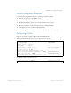
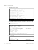
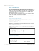
Table Of Contents
- Contents
- Figures
- Tables
- Preface
- Part 1: Basic Switching
- Accessing the Switch
- The Management Network
- Local Management Using the Console Port
- The Command Line Interface
- Remote Management Access
- Client IP Address Agents
- Securing Access to the Switch
- Setting Allowable Source IP Address Ranges
- RADIUS Authentication and Authorization
- TACACS+ Authentication
- LDAP Authentication and Authorization
- Secure Shell and Secure Copy
- Configuring SSH/SCP Features on the Switch
- Configuring the SCP Administrator Password
- Using SSH and SCP Client Commands
- SSH and SCP Encryption of Management Messages
- Generating RSA Host and Server Keys for SSH Access
- SSH/SCP Integration with Radius Authentication
- SSH/SCP Integration with TACACS+ Authentication
- End User Access Control
- Ports and Trunking
- Port-Based Network Access Control
- VLANs
- Spanning Tree Protocol
- RSTP and MSTP
- Link Layer Discovery Protocol
- Quality of Service
- Accessing the Switch
- Part 2: IP Routing
- Basic IP Routing
- Routing Information Protocol
- IGMP
- OSPF
- OSPF Overview
- OSPF Implementation in BLADE OS
- OSPF Configuration Examples
- Remote Monitoring
- Part 3: High Availability Fundamentals
- High Availability
- Layer 2 Failover
- Server Link Failure Detection
- VRRP Overview
- Failover Methods
- BLADE OS Extensions to VRRP
- Virtual Router Deployment Considerations
- High Availability Configurations
- High Availability
- Part 4: Appendices
- Index
BLADE OS 5.1 Application Guide
102 Chapter 4: VLANs BMD00113, September 2009
Port-Based vs. Protocol-Based VLANs
Each VLAN supports both port-based and protocol-based association, as follows:
The default VLAN configuration is port-based. All data ports are members of VLAN 1, with no
PVLAN association.
When you add ports to a PVLAN, the ports become members of both the port-based VLAN and
the PVLAN. For example, if you add port 20 to PVLAN 1 on VLAN 2, the port also becomes
a member of VLAN 2.
When you delete a PVLAN, it’s member ports remain members of the port-based VLAN. For
example, if you delete PVLAN 1 from VLAN 2, port 20 remains a member of VLAN 2.
When you delete a port from a VLAN, the port is deleted from all corresponding PVLANs.
PVLAN Priority Levels
You can assign each PVLAN a priority value of 0-7, used for Quality of Service (QoS). PVLAN
priority takes precedence over a port’s configured priority level. If no priority level is configured for
the PVLAN (priority = 0), each port’s priority is used (if configured).
All member ports of a PVLAN have the same PVLAN priority level.
PVLAN Tagging
When PVLAN tagging is enabled, the switch tags frames that match the PVLAN protocol. For
more information about tagging, see “VLAN Tagging” on page 90.
Untagged ports must have PVLAN tagging disabled. Tagged ports can have PVLAN tagging either
enabled or disabled.
PVLAN tagging has higher precedence than port-based tagging. If a port is tag enabled
(/cfg/port <x>/tag), and the port is a member of a PVLAN, the PVLAN tags egress frames
that match the PVLAN protocol.
Use the tag list command (/cfg/l2/vlan <x>/pvlan <x>/taglist) to define the
complete list of tag-enabled ports in the PVLAN. Note that all ports not included in the PVLAN tag
list will have PVLAN tagging disabled.