
BLADE OS™ Application Guide HP GbE2c Ethernet Blade Switch for c-Class BladeSystem Version 5.1 Advanced Functionality Software
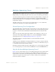
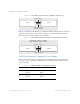
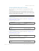
Table Of Contents
- Contents
- Figures
- Tables
- Preface
- Part 1: Basic Switching
- Accessing the Switch
- The Management Network
- Local Management Using the Console Port
- The Command Line Interface
- Remote Management Access
- Client IP Address Agents
- Securing Access to the Switch
- Setting Allowable Source IP Address Ranges
- RADIUS Authentication and Authorization
- TACACS+ Authentication
- LDAP Authentication and Authorization
- Secure Shell and Secure Copy
- Configuring SSH/SCP Features on the Switch
- Configuring the SCP Administrator Password
- Using SSH and SCP Client Commands
- SSH and SCP Encryption of Management Messages
- Generating RSA Host and Server Keys for SSH Access
- SSH/SCP Integration with Radius Authentication
- SSH/SCP Integration with TACACS+ Authentication
- End User Access Control
- Ports and Trunking
- Port-Based Network Access Control
- VLANs
- Spanning Tree Protocol
- RSTP and MSTP
- Link Layer Discovery Protocol
- Quality of Service
- Accessing the Switch
- Part 2: IP Routing
- Basic IP Routing
- Routing Information Protocol
- IGMP
- OSPF
- OSPF Overview
- OSPF Implementation in BLADE OS
- OSPF Configuration Examples
- Remote Monitoring
- Part 3: High Availability Fundamentals
- High Availability
- Layer 2 Failover
- Server Link Failure Detection
- VRRP Overview
- Failover Methods
- BLADE OS Extensions to VRRP
- Virtual Router Deployment Considerations
- High Availability Configurations
- High Availability
- Part 4: Appendices
- Index

BLADE OS 5.1 Application Guide
112 Chapter 5: Spanning Tree Protocol BMD00113, September 2009
Spanning Tree Group Configuration Guidelines
This section provides important information on configuring Spanning Tree Groups (STGs).
Default Spanning Tree configuration
In the default configuration, a single STG with the ID of 1 includes all ports on the switch, except
management port 19. STG 1 is called the default STG. All other STGs are empty, except
management STG 128, and VLANs must be added by the user.
You cannot assign ports directly to an STG. Add the ports to a VLAN, and add the VLAN to the
STG. STGs 1-127 are enabled by default and assigned an ID number from 1 to 127. STG 128 is
disabled by default, and contains the management VLAN 4095.
An STG cannot be deleted, only disabled. If you disable the STG while it still contains VLAN
members, Spanning Tree will be off on all ports belonging to that VLAN.
Adding a VLAN to an STG
If no VLANs exist beyond the default VLAN 1 see “Creating a VLAN” on page 112 for
information on adding ports to VLANs.
Add the VLAN to the STG using the following command:
/cfg/l2/stg <STG number>/add <VLAN number>
Note – To ensure proper operation with switches that use Cisco Per VLAN Spanning
Tree (PVST+), you must either create a separate STG for each VLAN, or manually add all
associated VLANs into a single STG.
Creating a VLAN
When you create a VLAN, that VLAN automatically belongs to STG 1, the default STG. If you
want the VLAN in another STG, you must move the VLAN by assigning it to another STG.
To move a newly created VLAN to an existing STG:
1. Create the VLAN
2. Add the VLAN to an existing STG