
BLADE OS™ Application Guide HP GbE2c Ethernet Blade Switch for c-Class BladeSystem Version 5.1 Advanced Functionality Software
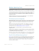
Table Of Contents
- Contents
- Figures
- Tables
- Preface
- Part 1: Basic Switching
- Accessing the Switch
- The Management Network
- Local Management Using the Console Port
- The Command Line Interface
- Remote Management Access
- Client IP Address Agents
- Securing Access to the Switch
- Setting Allowable Source IP Address Ranges
- RADIUS Authentication and Authorization
- TACACS+ Authentication
- LDAP Authentication and Authorization
- Secure Shell and Secure Copy
- Configuring SSH/SCP Features on the Switch
- Configuring the SCP Administrator Password
- Using SSH and SCP Client Commands
- SSH and SCP Encryption of Management Messages
- Generating RSA Host and Server Keys for SSH Access
- SSH/SCP Integration with Radius Authentication
- SSH/SCP Integration with TACACS+ Authentication
- End User Access Control
- Ports and Trunking
- Port-Based Network Access Control
- VLANs
- Spanning Tree Protocol
- RSTP and MSTP
- Link Layer Discovery Protocol
- Quality of Service
- Accessing the Switch
- Part 2: IP Routing
- Basic IP Routing
- Routing Information Protocol
- IGMP
- OSPF
- OSPF Overview
- OSPF Implementation in BLADE OS
- OSPF Configuration Examples
- Remote Monitoring
- Part 3: High Availability Fundamentals
- High Availability
- Layer 2 Failover
- Server Link Failure Detection
- VRRP Overview
- Failover Methods
- BLADE OS Extensions to VRRP
- Virtual Router Deployment Considerations
- High Availability Configurations
- High Availability
- Part 4: Appendices
- Index

BLADE OS 5.1 Application Guide
BMD00113, September 2009 Chapter 5: Spanning Tree Protocol 115
Multiple Spanning Trees
Each HP GbE2c Ethernet Blade Switch supports a maximum of 128 Spanning Tree Groups (STGs).
Multiple STGs provide multiple data paths, which can be used for load-balancing and redundancy.
You enable load balancing between two GbE2c modules using multiple STGs by configuring each
path with a different VLAN and then assigning each VLAN to a separate STG. Each STG is
independent. Each STG sends its own Bridge Protocol Data Units (BPDUs), and each STG must be
independently configured.
The STG, or bridge group, forms a loop-free topology that includes one or more virtual LANs
(VLANs). The switch supports 128 STGs running simultaneously.
Default Spanning Tree Configuration
The default STG is STG 1, which includes all non-management ports on the switch. STG 1 supports
IEEE 802.1D Spanning Tree Protocol and may contain more than one VLAN. Although ports can
be added to or deleted from the default STG, the default STG itself cannot be deleted from the
system.
STGs 2-128 support Per VLAN Spanning Tree (PVST+), and by default may contain only one
VLAN each. To use multiple VLANs in STGs 2-128, you must enable IEEE 802.1s Multiple
Spanning Tree Protocol (see “Multiple Spanning Tree Protocol” on page 125).
The default configuration of management STG 128 contains VLAN 4095 with internal
management port 19.
All STGs except the default STG 1 and management STG 128, are empty by default, and VLANs
must be added by the user. However, you cannot assign ports directly to an STG. Instead, add ports
to a VLAN first and then add the VLAN to the STG.
Each STG is enabled by default and assigned an ID number from 2 to 127. By default, the spanning
tree on the management ports is turned off in both STP/PVST+ mode and in MSTP/RSTP mode.
Why Do We Need Multiple Spanning Trees?
Figure 12 shows a simple example of why we need multiple Spanning Trees. This example assumes
that ports 20 and 21 are not part of a trunk group. Two VLANs (VLAN 1 and VLAN 2) exist
between Switch 1 and Switch 2. If the same Spanning Tree Group is enabled on both switches, the
switches see an apparent loop and block port 21 on Switch 2, which cuts off communication
between the switches for VLAN 2.