
BLADE OS™ Application Guide HP GbE2c Ethernet Blade Switch for c-Class BladeSystem Version 5.1 Advanced Functionality Software
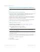
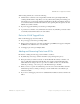
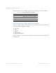
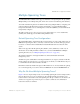
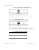
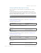
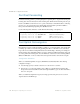
Table Of Contents
- Contents
- Figures
- Tables
- Preface
- Part 1: Basic Switching
- Accessing the Switch
- The Management Network
- Local Management Using the Console Port
- The Command Line Interface
- Remote Management Access
- Client IP Address Agents
- Securing Access to the Switch
- Setting Allowable Source IP Address Ranges
- RADIUS Authentication and Authorization
- TACACS+ Authentication
- LDAP Authentication and Authorization
- Secure Shell and Secure Copy
- Configuring SSH/SCP Features on the Switch
- Configuring the SCP Administrator Password
- Using SSH and SCP Client Commands
- SSH and SCP Encryption of Management Messages
- Generating RSA Host and Server Keys for SSH Access
- SSH/SCP Integration with Radius Authentication
- SSH/SCP Integration with TACACS+ Authentication
- End User Access Control
- Ports and Trunking
- Port-Based Network Access Control
- VLANs
- Spanning Tree Protocol
- RSTP and MSTP
- Link Layer Discovery Protocol
- Quality of Service
- Accessing the Switch
- Part 2: IP Routing
- Basic IP Routing
- Routing Information Protocol
- IGMP
- OSPF
- OSPF Overview
- OSPF Implementation in BLADE OS
- OSPF Configuration Examples
- Remote Monitoring
- Part 3: High Availability Fundamentals
- High Availability
- Layer 2 Failover
- Server Link Failure Detection
- VRRP Overview
- Failover Methods
- BLADE OS Extensions to VRRP
- Virtual Router Deployment Considerations
- High Availability Configurations
- High Availability
- Part 4: Appendices
- Index
BLADE OS 5.1 Application Guide
116 Chapter 5: Spanning Tree Protocol BMD00113, September 2009
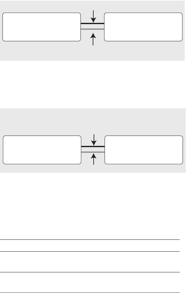
Figure 12 Two VLANs on One Instance of Spanning Tree Protocol
In Figure 13, VLAN 1 and VLAN 2 belong to different Spanning Tree Groups. The two instances of
spanning tree separate the topology without forming a loop, so that both VLANs can forward
packets between the switches without losing connectivity.
Figure 13 Two VLANs on Separate Instances of Spanning Tree Protocol
VLAN Participation in Spanning Tree Groups
Table 13 shows which switch ports participate in each Spanning Tree Group. By default, server
ports (ports 1-16) do not participate in Spanning Tree, even though they are members of their
respective VLANs.
Switch 2
20
21
Switch 1
20
21
VLAN 2, STG 1
is blocked by STP
VLAN 1, STG 1
X
Switch 2
20
21
Switch 1
20
21
VLAN 2, STG 2
VLAN 1, STG 1
Spanning Tree Group 1: VLAN 1
Spanning Tree Group 2: VLAN 2
Table 13 VLAN Participation in Spanning Tree Groups
VLAN 1 VLAN 2
Switch 1 Spanning Tree Group 1
Port 20
Spanning Tree Group 2
Port 21
Switch 2 Spanning Tree Group 1
Port 20
Spanning Tree Group 2
Port 21