
BLADE OS™ Application Guide HP GbE2c Ethernet Blade Switch for c-Class BladeSystem Version 5.1 Advanced Functionality Software
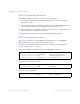
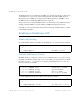
Table Of Contents
- Contents
- Figures
- Tables
- Preface
- Part 1: Basic Switching
- Accessing the Switch
- The Management Network
- Local Management Using the Console Port
- The Command Line Interface
- Remote Management Access
- Client IP Address Agents
- Securing Access to the Switch
- Setting Allowable Source IP Address Ranges
- RADIUS Authentication and Authorization
- TACACS+ Authentication
- LDAP Authentication and Authorization
- Secure Shell and Secure Copy
- Configuring SSH/SCP Features on the Switch
- Configuring the SCP Administrator Password
- Using SSH and SCP Client Commands
- SSH and SCP Encryption of Management Messages
- Generating RSA Host and Server Keys for SSH Access
- SSH/SCP Integration with Radius Authentication
- SSH/SCP Integration with TACACS+ Authentication
- End User Access Control
- Ports and Trunking
- Port-Based Network Access Control
- VLANs
- Spanning Tree Protocol
- RSTP and MSTP
- Link Layer Discovery Protocol
- Quality of Service
- Accessing the Switch
- Part 2: IP Routing
- Basic IP Routing
- Routing Information Protocol
- IGMP
- OSPF
- OSPF Overview
- OSPF Implementation in BLADE OS
- OSPF Configuration Examples
- Remote Monitoring
- Part 3: High Availability Fundamentals
- High Availability
- Layer 2 Failover
- Server Link Failure Detection
- VRRP Overview
- Failover Methods
- BLADE OS Extensions to VRRP
- Virtual Router Deployment Considerations
- High Availability Configurations
- High Availability
- Part 4: Appendices
- Index

BLADE OS 5.1 Application Guide
126 Chapter 6: RSTP and MSTP BMD00113, September 2009
MSTP Configuration Guidelines
When Multiple Spanning Tree Protocol is turned on, the following applies:
The switch automatically moves all VLANs from STP Group 1 to the Common Internal
Spanning Tree (CIST).
The switch automatically moves management VLAN 4095 to the CIST. When MSTP is turned
off, the switch moves VLAN 4095 from the CIST to Spanning Tree Group 128.
Region Name must be configured. By default, the revision level is set to 1. Each bridge in the
region must have the same name and revision level.
Each bridge in the region must have the same VLAN and STP Group mapping.
MSTP Configuration Example
This section provides steps to configure Multiple Spanning Tree Protocol on the HP GbE2c
Ethernet Blade Switch, using the Command-Line Interface (CLI).
1. Configure port and VLAN membership on the switch as described in “Configuring Ports and
VLANs on Example Switch 1” on page 97.
2. Set the mode to Multiple Spanning Tree, and configure MSTP region parameters.
3. Assign VLANs to Spanning Tree Groups.
4. Apply and save the configuration.
>> /cfg/l2/mrst (Select Multiple Spanning Tree menu)
>> Multiple Spanning Tree# mode mstp (Set mode to Multiple Spanning Trees)
>> Multiple Spanning Tree# on (Turn Multiple Spanning Trees on)
>> Multiple Spanning Tree# name <name> (Define the Region name)
>> /cfg/l2/stg 2 (Select Spanning Tree Group 2)
>> Spanning Tree Group 2# add 2 (Add VLAN 2)
>> Spanning Tree Group 2# apply (Apply the configurations)
>> Spanning Tree Group 2# save (Save the configurations)