
BLADE OS™ Application Guide HP GbE2c Ethernet Blade Switch for c-Class BladeSystem Version 5.1 Advanced Functionality Software


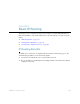

Table Of Contents
- Contents
- Figures
- Tables
- Preface
- Part 1: Basic Switching
- Accessing the Switch
- The Management Network
- Local Management Using the Console Port
- The Command Line Interface
- Remote Management Access
- Client IP Address Agents
- Securing Access to the Switch
- Setting Allowable Source IP Address Ranges
- RADIUS Authentication and Authorization
- TACACS+ Authentication
- LDAP Authentication and Authorization
- Secure Shell and Secure Copy
- Configuring SSH/SCP Features on the Switch
- Configuring the SCP Administrator Password
- Using SSH and SCP Client Commands
- SSH and SCP Encryption of Management Messages
- Generating RSA Host and Server Keys for SSH Access
- SSH/SCP Integration with Radius Authentication
- SSH/SCP Integration with TACACS+ Authentication
- End User Access Control
- Ports and Trunking
- Port-Based Network Access Control
- VLANs
- Spanning Tree Protocol
- RSTP and MSTP
- Link Layer Discovery Protocol
- Quality of Service
- Accessing the Switch
- Part 2: IP Routing
- Basic IP Routing
- Routing Information Protocol
- IGMP
- OSPF
- OSPF Overview
- OSPF Implementation in BLADE OS
- OSPF Configuration Examples
- Remote Monitoring
- Part 3: High Availability Fundamentals
- High Availability
- Layer 2 Failover
- Server Link Failure Detection
- VRRP Overview
- Failover Methods
- BLADE OS Extensions to VRRP
- Virtual Router Deployment Considerations
- High Availability Configurations
- High Availability
- Part 4: Appendices
- Index
BLADE OS 5.1 Application Guide
BMD00113, September 2009 Chapter 9: Basic IP Routing 159
Even if every end-station could be moved to better logical subnets (a daunting task), competition for
access to common server pools on different subnets still burdens the routers.
This problem is solved by using GbE2cs with built-in IP routing capabilities. Cross-subnet LAN
traffic can now be routed within the switches with wire speed Layer 2 switching performance. This
not only eases the load on the router but saves the network administrators from reconfiguring each
and every end-station with new IP addresses.
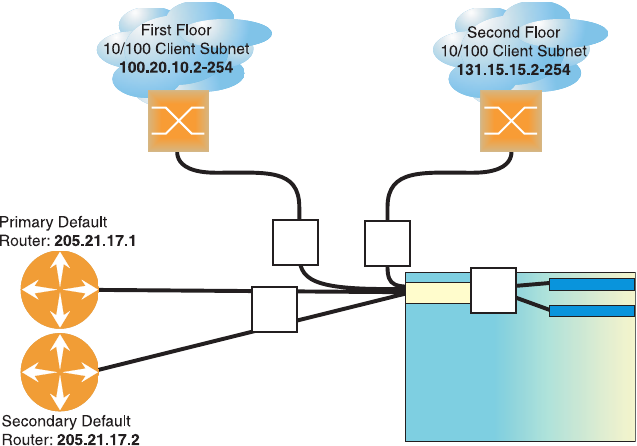
Take a closer look at the GbE2c in the following configuration example:
Figure 18 Switch-Based Routing Topology
The GbE2c connects the Gigabit Ethernet and Fast Ethernet trunks from various switched subnets
throughout one building. Common servers are placed on another subnet attached to the switch. A
primary and backup router are attached to the switch on yet another subnet.
Without Layer 3 IP routing on the switch, cross-subnet communication is relayed to the default
gateway (in this case, the router) for the next level of routing intelligence. The router fills in the
necessary address information and sends the data back to the switch, which then relays the packet to
the proper destination subnet using Layer 2 switching.
With Layer 3 IP routing in place on the GbE2c, routing between different IP subnets can be
accomplished entirely within the switch. This leaves the routers free to handle inbound and
outbound traffic for this group of subnets.
To make implementation even easier, UDP Jumbo frame traffic is automatically fragmented to
regular Ethernet frame sizes when routing to non-Jumbo frame VLANS or subnets. This automatic
frame conversion allows servers to communicate using Jumbo frames, all transparently to the user.
Se r v er Su b n e t :
206.30.15.2-254
206.30.15.2-254
IF #1
IF #1
IF #2
IF #2
IF #3
IF #3
IF #4
IF #4
10 Gbps
10 Gbps
Switch
Blade Chassis