
BLADE OS™ Application Guide HP GbE2c Ethernet Blade Switch for c-Class BladeSystem Version 5.1 Advanced Functionality Software
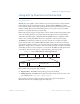
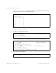


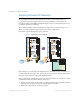
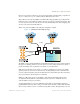
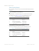
Table Of Contents
- Contents
- Figures
- Tables
- Preface
- Part 1: Basic Switching
- Accessing the Switch
- The Management Network
- Local Management Using the Console Port
- The Command Line Interface
- Remote Management Access
- Client IP Address Agents
- Securing Access to the Switch
- Setting Allowable Source IP Address Ranges
- RADIUS Authentication and Authorization
- TACACS+ Authentication
- LDAP Authentication and Authorization
- Secure Shell and Secure Copy
- Configuring SSH/SCP Features on the Switch
- Configuring the SCP Administrator Password
- Using SSH and SCP Client Commands
- SSH and SCP Encryption of Management Messages
- Generating RSA Host and Server Keys for SSH Access
- SSH/SCP Integration with Radius Authentication
- SSH/SCP Integration with TACACS+ Authentication
- End User Access Control
- Ports and Trunking
- Port-Based Network Access Control
- VLANs
- Spanning Tree Protocol
- RSTP and MSTP
- Link Layer Discovery Protocol
- Quality of Service
- Accessing the Switch
- Part 2: IP Routing
- Basic IP Routing
- Routing Information Protocol
- IGMP
- OSPF
- OSPF Overview
- OSPF Implementation in BLADE OS
- OSPF Configuration Examples
- Remote Monitoring
- Part 3: High Availability Fundamentals
- High Availability
- Layer 2 Failover
- Server Link Failure Detection
- VRRP Overview
- Failover Methods
- BLADE OS Extensions to VRRP
- Virtual Router Deployment Considerations
- High Availability Configurations
- High Availability
- Part 4: Appendices
- Index

BLADE OS 5.1 Application Guide
160 Chapter 9: Basic IP Routing BMD00113, September 2009
Subnet Routing Example
Prior to configuring, you must be connected to the switch Command Line Interface (CLI) as the
administrator.
Note – For details about accessing and using any of the menu commands described in this
example, see the BLADE OS 5.1 Command Reference.
1. Assign an IP address (or document the existing one) for each router and client workstation.
In the example topology in Figure 18 on page 159, the following IP addresses are used:
2. Assign an IP interface for each subnet attached to the switch.
Since there are four IP subnets connected to the switch, four IP interfaces are needed:
Table 21 Subnet Routing Example: IP Address Assignments
Subnet Devices IP Addresses
1 Primary and Secondary Default
Routers
205.21.17.1 and
205.21.17.2
2 First Floor Client Workstations 100.20.10.2-254
3 Second Floor Client Workstations 131.15.15.2-254
4 Common Servers 206.30.15.2-254
Table 22 Subnet Routing Example: IP Interface Assignments
Interface Devices IP Interface Address
IF 1 Primary and Secondary Default
Routers
205.21.17.3
IF 2 First Floor Client Workstations 100.20.10.1
IF 3 Second Floor Client Workstations 131.15.15.1
IF 4 Common Servers 206.30.15.1