
BLADE OS™ Application Guide HP GbE2c Ethernet Blade Switch for c-Class BladeSystem Version 5.1 Advanced Functionality Software
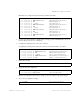
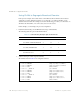
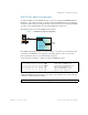
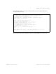
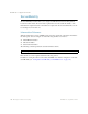
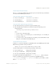
Table Of Contents
- Contents
- Figures
- Tables
- Preface
- Part 1: Basic Switching
- Accessing the Switch
- The Management Network
- Local Management Using the Console Port
- The Command Line Interface
- Remote Management Access
- Client IP Address Agents
- Securing Access to the Switch
- Setting Allowable Source IP Address Ranges
- RADIUS Authentication and Authorization
- TACACS+ Authentication
- LDAP Authentication and Authorization
- Secure Shell and Secure Copy
- Configuring SSH/SCP Features on the Switch
- Configuring the SCP Administrator Password
- Using SSH and SCP Client Commands
- SSH and SCP Encryption of Management Messages
- Generating RSA Host and Server Keys for SSH Access
- SSH/SCP Integration with Radius Authentication
- SSH/SCP Integration with TACACS+ Authentication
- End User Access Control
- Ports and Trunking
- Port-Based Network Access Control
- VLANs
- Spanning Tree Protocol
- RSTP and MSTP
- Link Layer Discovery Protocol
- Quality of Service
- Accessing the Switch
- Part 2: IP Routing
- Basic IP Routing
- Routing Information Protocol
- IGMP
- OSPF
- OSPF Overview
- OSPF Implementation in BLADE OS
- OSPF Configuration Examples
- Remote Monitoring
- Part 3: High Availability Fundamentals
- High Availability
- Layer 2 Failover
- Server Link Failure Detection
- VRRP Overview
- Failover Methods
- BLADE OS Extensions to VRRP
- Virtual Router Deployment Considerations
- High Availability Configurations
- High Availability
- Part 4: Appendices
- Index

BLADE OS 5.1 Application Guide
162 Chapter 9: Basic IP Routing BMD00113, September 2009
Using VLANs to Segregate Broadcast Domains
In the previous example, devices that share a common IP network are all in the same broadcast
domain. If you want to limit the broadcasts on your network, you could use VLANs to create
distinct broadcast domains. For example, as shown in the following procedure, you could create one
VLAN for the client trunks, one for the routers, and one for the servers.
In this example, you are adding to the previous configuration.
1. Determine which switch ports and IP interfaces belong to which VLANs.
The following table adds port and VLAN information:
2. Add the switch ports to their respective VLANs.
The VLANs shown in Table 23 are configured as follows:
Table 23 Subnet Routing Example: Optional VLAN Ports
VLAN Devices IP Interface Switch Port VLAN #
1 First Floor Client Workstations 2 20 1
Second Floor Client Workstations 3 21 1
2 Primary Default Router 1 22 2
Secondary Default Router 1 23 2
3 Common Servers 1 4 1 3
Common Servers 2 4 2 3
>> # /cfg/l2/vlan 1 (Select VLAN 1)
>> VLAN 1# add 20 (Add port for 1st floor to VLAN 1)
>> VLAN 1# add 21 (Add port for 2nd floor to VLAN 1)
>> VLAN 1# ena (Enable VLAN 1)
>> VLAN 1# ../vlan 2 (Select VLAN 2)
>> VLAN 2# add 22 (Add port for default router 1)
>> VLAN 2# add 23 (Add port for default router 2)
>> VLAN 2# ena (Enable VLAN 2)
>> VLAN 2# ../vlan 3 (Select VLAN 3)
>> VLAN 3# add 1 (Add port for default router 3)
>> VLAN 3# add 2 (Add port for common server 1)
>> VLAN 3# ena (Enable VLAN 3)