
BLADE OS™ Application Guide HP GbE2c Ethernet Blade Switch for c-Class BladeSystem Version 5.1 Advanced Functionality Software
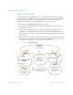
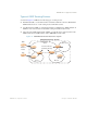
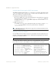
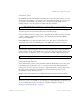
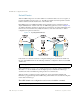
Table Of Contents
- Contents
- Figures
- Tables
- Preface
- Part 1: Basic Switching
- Accessing the Switch
- The Management Network
- Local Management Using the Console Port
- The Command Line Interface
- Remote Management Access
- Client IP Address Agents
- Securing Access to the Switch
- Setting Allowable Source IP Address Ranges
- RADIUS Authentication and Authorization
- TACACS+ Authentication
- LDAP Authentication and Authorization
- Secure Shell and Secure Copy
- Configuring SSH/SCP Features on the Switch
- Configuring the SCP Administrator Password
- Using SSH and SCP Client Commands
- SSH and SCP Encryption of Management Messages
- Generating RSA Host and Server Keys for SSH Access
- SSH/SCP Integration with Radius Authentication
- SSH/SCP Integration with TACACS+ Authentication
- End User Access Control
- Ports and Trunking
- Port-Based Network Access Control
- VLANs
- Spanning Tree Protocol
- RSTP and MSTP
- Link Layer Discovery Protocol
- Quality of Service
- Accessing the Switch
- Part 2: IP Routing
- Basic IP Routing
- Routing Information Protocol
- IGMP
- OSPF
- OSPF Overview
- OSPF Implementation in BLADE OS
- OSPF Configuration Examples
- Remote Monitoring
- Part 3: High Availability Fundamentals
- High Availability
- Layer 2 Failover
- Server Link Failure Detection
- VRRP Overview
- Failover Methods
- BLADE OS Extensions to VRRP
- Virtual Router Deployment Considerations
- High Availability Configurations
- High Availability
- Part 4: Appendices
- Index
BLADE OS 5.1 Application Guide
192 Chapter 12: OSPF BMD00113, September 2009
Types of OSPF Areas
An AS can be broken into logical units known as areas. In any AS with multiple areas, one area
must be designated as area 0, known as the backbone. The backbone acts as the central OSPF area.
All other areas in the AS must be connected to the backbone. Areas inject summary routing
information into the backbone, which then distributes it to other areas as needed.
As shown in Figure 20, OSPF defines the following types of areas:
Stub Area—an area that is connected to only one other area. External route information is not
distributed into stub areas.
Not-So-Stubby-Area (NSSA)—similar to a stub area with additional capabilities. Routes
originating from within the NSSA can be propagated to adjacent transit and backbone areas.
External routes from outside the AS can be advertised within the NSSA but are not distributed
into other areas.
Transit Area—an area that allows area summary information to be exchanged between routing
devices. The backbone (area 0), any area that contains a virtual link to connect two areas, and
any area that is not a stub area or an NSSA are considered transit areas.
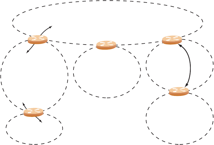
Figure 20 OSPF Area Types
Backbone
Area 0
Stub Area
Not-So-Stubby Area
(NSSA)
Transit Area
No External Routes
from Backbone
Stub Area, NSSA,
or Transit Area
Connected to Backbone
via Virtual Link
(Also a Transit Area)
External LSA
Routes
Internal LSA
Routes
ABR
ABR
ABR
ASBR
Non-OSPF Area
RIP/BGP AS
Virtual
Link
ABR
ABR = Area Border Router
ASBR = Autonomous System
Boundary Router