
BLADE OS™ Application Guide HP GbE2c Ethernet Blade Switch for c-Class BladeSystem Version 5.1 Advanced Functionality Software
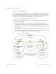
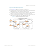
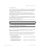
Table Of Contents
- Contents
- Figures
- Tables
- Preface
- Part 1: Basic Switching
- Accessing the Switch
- The Management Network
- Local Management Using the Console Port
- The Command Line Interface
- Remote Management Access
- Client IP Address Agents
- Securing Access to the Switch
- Setting Allowable Source IP Address Ranges
- RADIUS Authentication and Authorization
- TACACS+ Authentication
- LDAP Authentication and Authorization
- Secure Shell and Secure Copy
- Configuring SSH/SCP Features on the Switch
- Configuring the SCP Administrator Password
- Using SSH and SCP Client Commands
- SSH and SCP Encryption of Management Messages
- Generating RSA Host and Server Keys for SSH Access
- SSH/SCP Integration with Radius Authentication
- SSH/SCP Integration with TACACS+ Authentication
- End User Access Control
- Ports and Trunking
- Port-Based Network Access Control
- VLANs
- Spanning Tree Protocol
- RSTP and MSTP
- Link Layer Discovery Protocol
- Quality of Service
- Accessing the Switch
- Part 2: IP Routing
- Basic IP Routing
- Routing Information Protocol
- IGMP
- OSPF
- OSPF Overview
- OSPF Implementation in BLADE OS
- OSPF Configuration Examples
- Remote Monitoring
- Part 3: High Availability Fundamentals
- High Availability
- Layer 2 Failover
- Server Link Failure Detection
- VRRP Overview
- Failover Methods
- BLADE OS Extensions to VRRP
- Virtual Router Deployment Considerations
- High Availability Configurations
- High Availability
- Part 4: Appendices
- Index
BLADE OS 5.1 Application Guide
200 Chapter 12: OSPF BMD00113, September 2009
Default Routes
When an OSPF routing device encounters traffic for a destination address it does not recognize, it
forwards that traffic along the default route. Typically, the default route leads upstream toward the
backbone until it reaches the intended area or an external router.
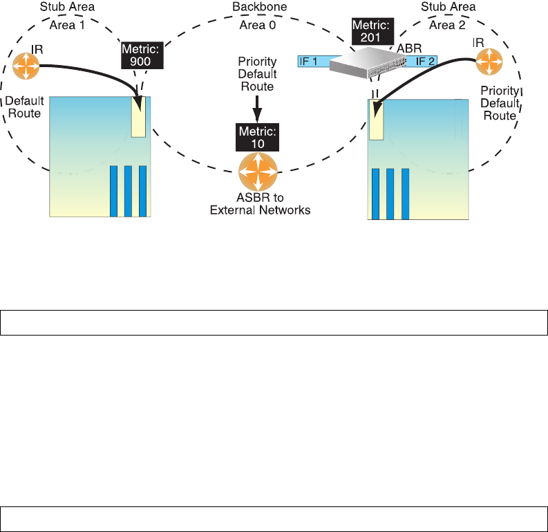
Each GbE2c acting as an ABR automatically inserts a default route into each attached area. In
simple OSPF stub areas or NSSAs with only one ABR leading upstream (see Area 1 in Figure 22),
any traffic for IP address destinations outside the area is forwarded to the switch’s IP interface, and
then into the connected transit area (usually the backbone). Since this is automatic, no further
configuration is required for such areas.
Figure 22 Injecting Default Routes
If the switch is in a transit area and has a configured default gateway, it can inject a default route
into rest of the OSPF domain. Use the following command to configure the switch to inject OSPF
default routes:
In the command above, <metric value> sets the priority for choosing this switch for default route.
The value none sets no default and 1 sets the highest priority for default route. Metric type
determines the method for influencing routing decisions for external routes.
When the switch is configured to inject a default route, an AS-external LSA with link state
ID 0.0.0.0 is propagated throughout the OSPF routing domain. This LSA is sent with the configured
metric value and metric type.
The OSPF default route configuration can be removed with the command:
Blade Chassis
Blade Chassis
>> # /cfg/l3/ospf/default <metric value> <metric type (1 or 2)>
>> # /cfg/l3/ospf/default none