
BLADE OS™ Application Guide HP GbE2c Ethernet Blade Switch for c-Class BladeSystem Version 5.1 Advanced Functionality Software
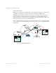
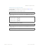
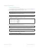
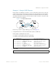
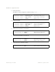
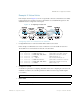
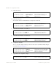
Table Of Contents
- Contents
- Figures
- Tables
- Preface
- Part 1: Basic Switching
- Accessing the Switch
- The Management Network
- Local Management Using the Console Port
- The Command Line Interface
- Remote Management Access
- Client IP Address Agents
- Securing Access to the Switch
- Setting Allowable Source IP Address Ranges
- RADIUS Authentication and Authorization
- TACACS+ Authentication
- LDAP Authentication and Authorization
- Secure Shell and Secure Copy
- Configuring SSH/SCP Features on the Switch
- Configuring the SCP Administrator Password
- Using SSH and SCP Client Commands
- SSH and SCP Encryption of Management Messages
- Generating RSA Host and Server Keys for SSH Access
- SSH/SCP Integration with Radius Authentication
- SSH/SCP Integration with TACACS+ Authentication
- End User Access Control
- Ports and Trunking
- Port-Based Network Access Control
- VLANs
- Spanning Tree Protocol
- RSTP and MSTP
- Link Layer Discovery Protocol
- Quality of Service
- Accessing the Switch
- Part 2: IP Routing
- Basic IP Routing
- Routing Information Protocol
- IGMP
- OSPF
- OSPF Overview
- OSPF Implementation in BLADE OS
- OSPF Configuration Examples
- Remote Monitoring
- Part 3: High Availability Fundamentals
- High Availability
- Layer 2 Failover
- Server Link Failure Detection
- VRRP Overview
- Failover Methods
- BLADE OS Extensions to VRRP
- Virtual Router Deployment Considerations
- High Availability Configurations
- High Availability
- Part 4: Appendices
- Index

BLADE OS 5.1 Application Guide
BMD00113, September 2009 Chapter 12: OSPF 201
Virtual Links
Usually, all areas in an OSPF AS are physically connected to the backbone. In some cases where
this is not possible, you can use a virtual link. Virtual links are created to connect one area to the
backbone through another non-backbone area (see Figure 20 on page 192).
The area which contains a virtual link must be a transit area and have full routing information.
Virtual links cannot be configured inside a stub area or NSSA. The area type must be defined as
transit using the following command:
The virtual link must be configured on the routing devices at each endpoint of the virtual link, though
they may traverse multiple routing devices. To configure a GbE2c as one endpoint of a virtual link,
use the following command:
where <link number> is a value between 1 and 3, <area index> is the OSPF area index of the
transit area, and <router ID> is the IP address of the virtual neighbor (nbr), the routing device at the
target endpoint. Another router ID is needed when configuring a virtual link in the other direction.
To provide the GbE2c with a router ID, see the following section Router ID.
For a detailed configuration example on Virtual Links, see “Example 2: Virtual Links” on page 209.
Router ID
Routing devices in OSPF areas are identified by a router ID. The router ID is expressed in IP
address format. The IP address of the router ID is not required to be included in any IP interface
range or in any OSPF area, and may even use the GbE2c loopback interface.
The router ID can be configured in one of the following two ways:
Dynamically—OSPF protocol configures the lowest IP interface IP address as the router ID.
This is the default.
Statically—Use the following command to manually configure the router ID:
To modify the router ID from static to dynamic, set the router ID to 0.0.0.0, save the configura-
tion, and reboot the GbE2c. To view the router ID, enter:
>> # /cfg/l3/ospf/aindex <area index>/type transit
>> # /cfg/l3/ospf/virt <link number>/aindex <area index>/nbr <router ID>
>> # /cfg/l3/rtrid <IP address>
>> # /info/l3/ospf/gen