
BLADE OS™ Application Guide HP GbE2c Ethernet Blade Switch for c-Class BladeSystem Version 5.1 Advanced Functionality Software
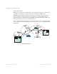
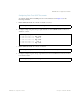
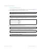
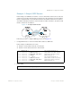
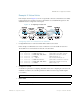
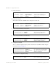
Table Of Contents
- Contents
- Figures
- Tables
- Preface
- Part 1: Basic Switching
- Accessing the Switch
- The Management Network
- Local Management Using the Console Port
- The Command Line Interface
- Remote Management Access
- Client IP Address Agents
- Securing Access to the Switch
- Setting Allowable Source IP Address Ranges
- RADIUS Authentication and Authorization
- TACACS+ Authentication
- LDAP Authentication and Authorization
- Secure Shell and Secure Copy
- Configuring SSH/SCP Features on the Switch
- Configuring the SCP Administrator Password
- Using SSH and SCP Client Commands
- SSH and SCP Encryption of Management Messages
- Generating RSA Host and Server Keys for SSH Access
- SSH/SCP Integration with Radius Authentication
- SSH/SCP Integration with TACACS+ Authentication
- End User Access Control
- Ports and Trunking
- Port-Based Network Access Control
- VLANs
- Spanning Tree Protocol
- RSTP and MSTP
- Link Layer Discovery Protocol
- Quality of Service
- Accessing the Switch
- Part 2: IP Routing
- Basic IP Routing
- Routing Information Protocol
- IGMP
- OSPF
- OSPF Overview
- OSPF Implementation in BLADE OS
- OSPF Configuration Examples
- Remote Monitoring
- Part 3: High Availability Fundamentals
- High Availability
- Layer 2 Failover
- Server Link Failure Detection
- VRRP Overview
- Failover Methods
- BLADE OS Extensions to VRRP
- Virtual Router Deployment Considerations
- High Availability Configurations
- High Availability
- Part 4: Appendices
- Index

BLADE OS 5.1 Application Guide
204 Chapter 12: OSPF BMD00113, September 2009
Configuring MD5 Authentication
Use the following commands to configure MD5 authentication on the switches shown in Figure 23:
1. Enable OSPF MD5 authentication for Area 0 on switches 1, 2, and 3.
2. Configure MD5 key ID for Area 0 on switches 1, 2, and 3.
3. Assign MD5 key ID to OSPF interfaces on switches 1, 2, and 3.
4. Enable OSPF MD5 authentication for Area 2 on switch 4.
5. Configure MD5 key for the virtual link between Area 2 and Area 0 on switches 2 and 4.
6. Assign MD5 key ID to OSPF virtual link on switches 2 and 4.
>> # /cfg/l3/ospf/aindex 0/auth md5 (Turn on MD5 authentication)
>> #
/cfg/l3/ospf/md5key 1/key test
>> # /cfg/l3/ospf/if 1
>> OSPF Interface 1 # mdkey 1
>> OSPF Interface 1 # ../if 2
>> OSPF Interface 2 # mdkey 1
>> OSPF Interface 2 # ../if 3
>> OSPF Interface 3 # mdkey 1
>> # /cfg/l3/ospf/aindex 2/auth md5
>> # /cfg/l3/ospf/md5key 2/key blade
>> # /cfg/l3/ospf/virt 1/mdkey 2