
BLADE OS™ Application Guide HP GbE2c Ethernet Blade Switch for c-Class BladeSystem Version 5.1 Advanced Functionality Software
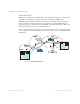
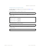
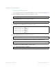
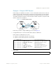
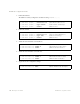
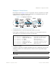
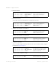
Table Of Contents
- Contents
- Figures
- Tables
- Preface
- Part 1: Basic Switching
- Accessing the Switch
- The Management Network
- Local Management Using the Console Port
- The Command Line Interface
- Remote Management Access
- Client IP Address Agents
- Securing Access to the Switch
- Setting Allowable Source IP Address Ranges
- RADIUS Authentication and Authorization
- TACACS+ Authentication
- LDAP Authentication and Authorization
- Secure Shell and Secure Copy
- Configuring SSH/SCP Features on the Switch
- Configuring the SCP Administrator Password
- Using SSH and SCP Client Commands
- SSH and SCP Encryption of Management Messages
- Generating RSA Host and Server Keys for SSH Access
- SSH/SCP Integration with Radius Authentication
- SSH/SCP Integration with TACACS+ Authentication
- End User Access Control
- Ports and Trunking
- Port-Based Network Access Control
- VLANs
- Spanning Tree Protocol
- RSTP and MSTP
- Link Layer Discovery Protocol
- Quality of Service
- Accessing the Switch
- Part 2: IP Routing
- Basic IP Routing
- Routing Information Protocol
- IGMP
- OSPF
- OSPF Overview
- OSPF Implementation in BLADE OS
- OSPF Configuration Examples
- Remote Monitoring
- Part 3: High Availability Fundamentals
- High Availability
- Layer 2 Failover
- Server Link Failure Detection
- VRRP Overview
- Failover Methods
- BLADE OS Extensions to VRRP
- Virtual Router Deployment Considerations
- High Availability Configurations
- High Availability
- Part 4: Appendices
- Index
BLADE OS 5.1 Application Guide
BMD00113, September 2009 Chapter 12: OSPF 207
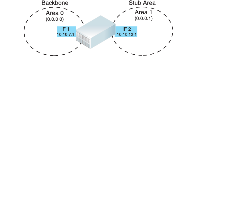
Example 1: Simple OSPF Domain
In this example, two OSPF areas are defined—one area is the backbone and the other is a stub area.
A stub area does not allow advertisements of external routes, thus reducing the size of the database.
Instead, a default summary route of IP address 0.0.0.0 is automatically inserted into the stub area.
Any traffic for IP address destinations outside the stub area will be forwarded to the stub area’s IP
interface, and then into the backbone.
Figure 24 A Simple OSPF Domain
Follow this procedure to configure OSPF support as shown in Figure 24:
1. Configure IP interfaces on each network that will be attached to OSPF areas.
In this example, two IP interfaces are needed:
Interface 1 for the backbone network on 10.10.7.0/24
Interface 2 for the stub area network on 10.10.12.0/24.
2. Enable OSPF.
Network
10.10.12.0/24
10.10.7.0/24
Network
Blade Chassis
Blade Chassis
>> # /cfg/l3/if 1 (Select menu for IP interface 1)
>> IP Interface 1 # addr 10.10.7.1 (Set IP address on backbone network)
>> IP Interface 1 # mask 255.255.255.0 (Set IP mask on backbone network)
>> IP Interface 1 # enable (Enable IP interface 1)
>> IP Interface 1 # ../if 2 (Select menu for IP interface 2)
>> IP Interface 2 # addr 10.10.12.1 (Set IP address on stub area network)
>> IP Interface 2 # mask 255.255.255.0 (Set IP mask on stub area network)
>> IP Interface 2 # enable (Enable IP interface 2)
>> IP Interface 2 # /cfg/l3/ospf/on (Enable OSPF on the switch)