
BLADE OS™ Application Guide HP GbE2c Ethernet Blade Switch for c-Class BladeSystem Version 5.1 Advanced Functionality Software
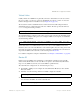
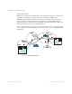
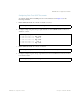
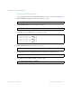
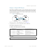
Table Of Contents
- Contents
- Figures
- Tables
- Preface
- Part 1: Basic Switching
- Accessing the Switch
- The Management Network
- Local Management Using the Console Port
- The Command Line Interface
- Remote Management Access
- Client IP Address Agents
- Securing Access to the Switch
- Setting Allowable Source IP Address Ranges
- RADIUS Authentication and Authorization
- TACACS+ Authentication
- LDAP Authentication and Authorization
- Secure Shell and Secure Copy
- Configuring SSH/SCP Features on the Switch
- Configuring the SCP Administrator Password
- Using SSH and SCP Client Commands
- SSH and SCP Encryption of Management Messages
- Generating RSA Host and Server Keys for SSH Access
- SSH/SCP Integration with Radius Authentication
- SSH/SCP Integration with TACACS+ Authentication
- End User Access Control
- Ports and Trunking
- Port-Based Network Access Control
- VLANs
- Spanning Tree Protocol
- RSTP and MSTP
- Link Layer Discovery Protocol
- Quality of Service
- Accessing the Switch
- Part 2: IP Routing
- Basic IP Routing
- Routing Information Protocol
- IGMP
- OSPF
- OSPF Overview
- OSPF Implementation in BLADE OS
- OSPF Configuration Examples
- Remote Monitoring
- Part 3: High Availability Fundamentals
- High Availability
- Layer 2 Failover
- Server Link Failure Detection
- VRRP Overview
- Failover Methods
- BLADE OS Extensions to VRRP
- Virtual Router Deployment Considerations
- High Availability Configurations
- High Availability
- Part 4: Appendices
- Index
BLADE OS 5.1 Application Guide
BMD00113, September 2009 Chapter 12: OSPF 209
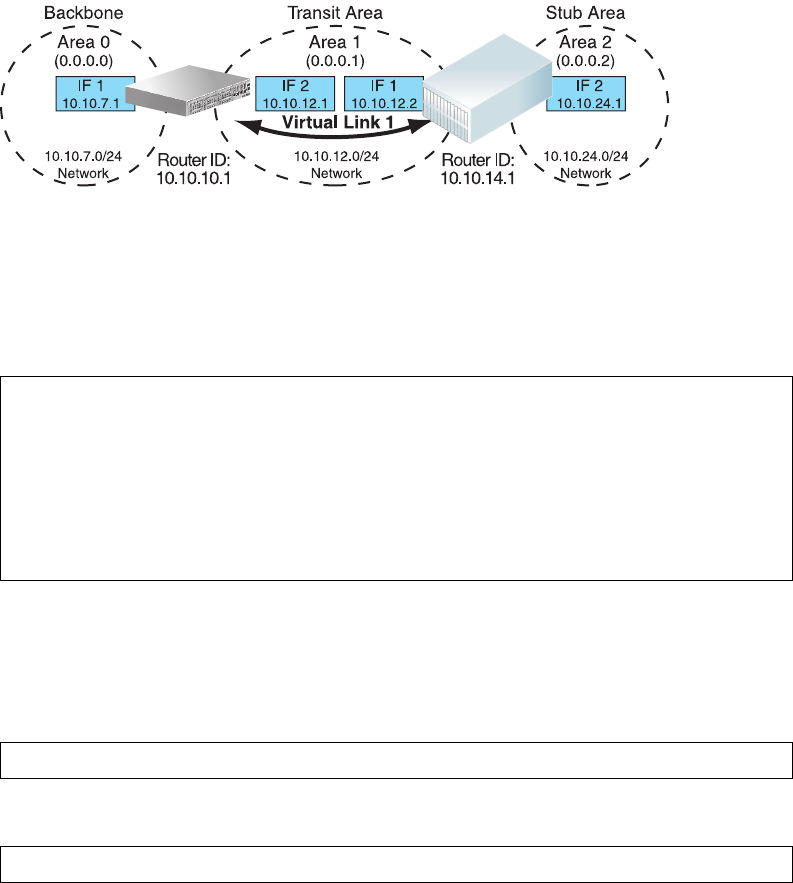
Example 2: Virtual Links
In the example shown in Figure 25, area 2 is not physically connected to the backbone as is usually
required. Instead, area 2 will be connected to the backbone via a virtual link through area 1. The
virtual link must be configured at each endpoint.
Figure 25 Configuring a Virtual Link
Configuring OSPF for a Virtual Link on Switch #1
1. Configure IP interfaces on each network that will be attached to the switch.
In this example, two IP interfaces are needed on Switch #1: one for the backbone network on
10.10.7.0/24 and one for the transit area network on 10.10.12.0/24.
2. Configure the router ID.
A router ID is required when configuring virtual links. Later, when configuring the other end of the
virtual link on Switch 2, the router ID specified here will be used as the target virtual neighbor
(nbr) address.
3. Enable OSPF.
Application
Switch 1
Application
Switch 1
Switch 2
Switch 2
Blade Chassis
Blade Chassis
>> # /cfg/l3/if 1 (Select menu for IP interface 1)
>> IP Interface 1 # addr 10.10.7.1 (Set IP address on backbone network)
>> IP Interface 1 # mask 255.255.255.0 (Set IP mask on backbone network)
>> IP Interface 1 # enable (Enable IP interface 1)
>> IP Interface 1 # ../if 2 (Select menu for IP interface 2)
>> IP Interface 2 # addr 10.10.12.1 (Set IP address on transit area network)
>> IP Interface 2 # mask 255.255.255.0 (Set IP mask on transit area network)
>> IP Interface 2 # enable (Enable interface 2)
>> IP Interface 2 # /cfg/l3/rtrid 10.10.10.1
(Set static router ID on switch 1)
>> IP # /cfg/l3/ospf/on (Enable OSPF on switch 1)