
BLADE OS™ Application Guide HP GbE2c Ethernet Blade Switch for c-Class BladeSystem Version 5.1 Advanced Functionality Software
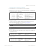
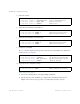
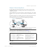
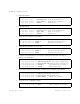

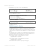
Table Of Contents
- Contents
- Figures
- Tables
- Preface
- Part 1: Basic Switching
- Accessing the Switch
- The Management Network
- Local Management Using the Console Port
- The Command Line Interface
- Remote Management Access
- Client IP Address Agents
- Securing Access to the Switch
- Setting Allowable Source IP Address Ranges
- RADIUS Authentication and Authorization
- TACACS+ Authentication
- LDAP Authentication and Authorization
- Secure Shell and Secure Copy
- Configuring SSH/SCP Features on the Switch
- Configuring the SCP Administrator Password
- Using SSH and SCP Client Commands
- SSH and SCP Encryption of Management Messages
- Generating RSA Host and Server Keys for SSH Access
- SSH/SCP Integration with Radius Authentication
- SSH/SCP Integration with TACACS+ Authentication
- End User Access Control
- Ports and Trunking
- Port-Based Network Access Control
- VLANs
- Spanning Tree Protocol
- RSTP and MSTP
- Link Layer Discovery Protocol
- Quality of Service
- Accessing the Switch
- Part 2: IP Routing
- Basic IP Routing
- Routing Information Protocol
- IGMP
- OSPF
- OSPF Overview
- OSPF Implementation in BLADE OS
- OSPF Configuration Examples
- Remote Monitoring
- Part 3: High Availability Fundamentals
- High Availability
- Layer 2 Failover
- Server Link Failure Detection
- VRRP Overview
- Failover Methods
- BLADE OS Extensions to VRRP
- Virtual Router Deployment Considerations
- High Availability Configurations
- High Availability
- Part 4: Appendices
- Index

BLADE OS 5.1 Application Guide
212 Chapter 12: OSPF BMD00113, September 2009
6. Define the stub area.
7. Attach the network interface to the backbone.
8. Attach the network interface to the transit area.
9. Configure the virtual link.
The nbr router ID configured in this step must be the same as the router ID that was configured for
switch #1 in Step 2 on page 209.
10. Apply and save the configuration changes.
Other Virtual Link Options
You can use redundant paths by configuring multiple virtual links.
Only the endpoints of the virtual link are configured. The virtual link path may traverse
multiple routers in an area as long as there is a routable path between the endpoints.
>> OSPF Area (index) 1 # ../aindex 2 (Select the menu for area index 2)
>> OSPF Area (index) 2 # areaid 0.0.0.2 (Set the area ID for OSPF area 2)
>> OSPF Area (index) 2 # type stub (Define area as stub type)
>> OSPF Area (index) 2 # enable (Enable the area)
>> OSPF Area (index) 2 # ../if 1 (Select OSPF menu for IP interface 1)
>> OSPF Interface 1 # aindex 1 (Attach network to transit area index)
>> OSPF Interface 1 # enable (Enable the transit area interface)
>> OSPF Interface 1 # ../if 2 (Select OSPF menu for IP interface 2)
>> OSPF Interface 2 # aindex 2 (Attach network to stub area index)
>> OSPF Interface 2 # enable (Enable the stub area interface)
>> OSPF Interface 2 # ../virt 1 (Specify a virtual link number)
>> OSPF Virtual Link 1 # aindex 1 (Specify transit area for the virtual link)
>> OSPF Virtual Link 1 # nbr 10.10.10.1 (Specify the router ID of the recipient)
>> OSPF Virtual Link 1 # enable
(Enable the virtual link)
>> OSPF Interface 2 # apply (Global command to apply all changes)
>> OSPF Interface 2 # save (Global command to save all changes)