
BLADE OS™ Application Guide HP GbE2c Ethernet Blade Switch for c-Class BladeSystem Version 5.1 Advanced Functionality Software
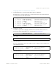
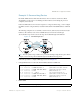

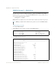
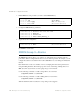
Table Of Contents
- Contents
- Figures
- Tables
- Preface
- Part 1: Basic Switching
- Accessing the Switch
- The Management Network
- Local Management Using the Console Port
- The Command Line Interface
- Remote Management Access
- Client IP Address Agents
- Securing Access to the Switch
- Setting Allowable Source IP Address Ranges
- RADIUS Authentication and Authorization
- TACACS+ Authentication
- LDAP Authentication and Authorization
- Secure Shell and Secure Copy
- Configuring SSH/SCP Features on the Switch
- Configuring the SCP Administrator Password
- Using SSH and SCP Client Commands
- SSH and SCP Encryption of Management Messages
- Generating RSA Host and Server Keys for SSH Access
- SSH/SCP Integration with Radius Authentication
- SSH/SCP Integration with TACACS+ Authentication
- End User Access Control
- Ports and Trunking
- Port-Based Network Access Control
- VLANs
- Spanning Tree Protocol
- RSTP and MSTP
- Link Layer Discovery Protocol
- Quality of Service
- Accessing the Switch
- Part 2: IP Routing
- Basic IP Routing
- Routing Information Protocol
- IGMP
- OSPF
- OSPF Overview
- OSPF Implementation in BLADE OS
- OSPF Configuration Examples
- Remote Monitoring
- Part 3: High Availability Fundamentals
- High Availability
- Layer 2 Failover
- Server Link Failure Detection
- VRRP Overview
- Failover Methods
- BLADE OS Extensions to VRRP
- Virtual Router Deployment Considerations
- High Availability Configurations
- High Availability
- Part 4: Appendices
- Index
BLADE OS 5.1 Application Guide
BMD00113, September 2009 Chapter 12: OSPF 213
Example 3: Summarizing Routes
By default, ABRs advertise all the network addresses from one area into another area. Route
summarization can be used for consolidating advertised addresses and reducing the perceived
complexity of the network.
If the network IP addresses in an area are assigned to a contiguous subnet range, you can configure
the ABR to advertise a single summary route that includes all the individual IP addresses within the
area.
The following example shows one summary route from area 1 (stub area) injected into area 0 (the
backbone). The summary route consists of all IP addresses from 36.128.192.0 through
36.128.254.255 except for the routes in the range 36.128.200.0 through 36.128.200.255.
Figure 26 Summarizing Routes
Note – You can specify a range of addresses to prevent advertising by using the hide option. In this
example, routes in the range 36.128.200.0 through 36.128.200.255 are kept private.
Follow this procedure to configure OSPF support as shown in Figure 26:
1. Configure IP interfaces for each network which will be attached to OSPF areas.
2. Enable OSPF.
Blade Chassis
Blade Chassis
>> # /cfg/l3/if 1 (Select menu for IP interface 1)
>> IP Interface 1 # addr 10.10.7.1 (Set IP address on backbone network)
>
> IP Interface 1 # mask 255.255.255.0 (Set IP mask on backbone network)
>> IP Interface 1 # ena (Enable IP interface 1)
>> IP Interface 1 # ../if 2 (Select menu for IP interface 2)
>> IP Interface 2 # addr 36.128.192.1 (Set IP address on stub area network)
>
> IP Interface 2 # mask 255.255.192.0 (Set IP mask on stub area network)
>> IP Interface 2 # ena (Enable IP interface 2)
>> IP Interface 2 # /cfg/l3/ospf/on
(Enable OSPF on the switch)