
BLADE OS™ Application Guide HP GbE2c Ethernet Blade Switch for c-Class BladeSystem Version 5.1 Advanced Functionality Software
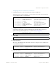
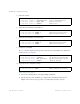
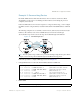
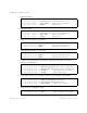

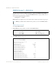
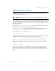
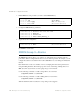
Table Of Contents
- Contents
- Figures
- Tables
- Preface
- Part 1: Basic Switching
- Accessing the Switch
- The Management Network
- Local Management Using the Console Port
- The Command Line Interface
- Remote Management Access
- Client IP Address Agents
- Securing Access to the Switch
- Setting Allowable Source IP Address Ranges
- RADIUS Authentication and Authorization
- TACACS+ Authentication
- LDAP Authentication and Authorization
- Secure Shell and Secure Copy
- Configuring SSH/SCP Features on the Switch
- Configuring the SCP Administrator Password
- Using SSH and SCP Client Commands
- SSH and SCP Encryption of Management Messages
- Generating RSA Host and Server Keys for SSH Access
- SSH/SCP Integration with Radius Authentication
- SSH/SCP Integration with TACACS+ Authentication
- End User Access Control
- Ports and Trunking
- Port-Based Network Access Control
- VLANs
- Spanning Tree Protocol
- RSTP and MSTP
- Link Layer Discovery Protocol
- Quality of Service
- Accessing the Switch
- Part 2: IP Routing
- Basic IP Routing
- Routing Information Protocol
- IGMP
- OSPF
- OSPF Overview
- OSPF Implementation in BLADE OS
- OSPF Configuration Examples
- Remote Monitoring
- Part 3: High Availability Fundamentals
- High Availability
- Layer 2 Failover
- Server Link Failure Detection
- VRRP Overview
- Failover Methods
- BLADE OS Extensions to VRRP
- Virtual Router Deployment Considerations
- High Availability Configurations
- High Availability
- Part 4: Appendices
- Index

BLADE OS 5.1 Application Guide
220 Chapter 13: Remote Monitoring BMD00113, September 2009
1. Enable RMON on each port where you wish to collect RMON History.
2. Configure the RMON History parameters.
3. Apply and save the configuration.
Use SNMP to view the data.
RMON Group 3—Alarms
The RMON Alarm Group allows you to define a set of thresholds used to determine network
performance. When a configured threshold is crossed, an alarm is generated. For example, you can
configure the switch to issue an alarm if more than 1,000 CRC errors occur during a 10-minute time
interval.
Each Alarm index consists of a variable to monitor, a sampling time interval, and parameters for
rising and falling thresholds. The Alarm group can be used to track rising or falling values for a
MIB object. The object must be a counter, gauge, integer, or time interval.
Use the following command to correlate a rising alarm to an event index:
/cfg/rmon/alarm <x>/revtidx
Use the following command to correlate a falling alarm to an event index:
/cfg/rmon/alarm <x>/fevtidx
When the alarm threshold is reached, the corresponding event is triggered.
>> # /cfg/port 20/rmon (Select Port 20 RMON)
>> Port 20# ena (Enable RMON)
>> Port 20 RMON# apply (Make your changes active)
>> Port 20 RMON# save (Save for restore after reboot)
>> # /cfg/rmon/hist 1 (Select RMON History 1)
>> RMON History 1# ifoid 1.3.6.1.2.1.2.2.1.1.20
>> RMON History 1# rbnum 30
>> RMON History 1# intrval 120
>> RMON History 1# owner "Owner_History_1"
>> RMON History 1# apply (Make your changes active)
>> RMON History 1# save (Save for restore after reboot)