
BLADE OS™ Application Guide HP GbE2c Ethernet Blade Switch for c-Class BladeSystem Version 5.1 Advanced Functionality Software


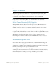
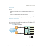
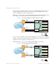
Table Of Contents
- Contents
- Figures
- Tables
- Preface
- Part 1: Basic Switching
- Accessing the Switch
- The Management Network
- Local Management Using the Console Port
- The Command Line Interface
- Remote Management Access
- Client IP Address Agents
- Securing Access to the Switch
- Setting Allowable Source IP Address Ranges
- RADIUS Authentication and Authorization
- TACACS+ Authentication
- LDAP Authentication and Authorization
- Secure Shell and Secure Copy
- Configuring SSH/SCP Features on the Switch
- Configuring the SCP Administrator Password
- Using SSH and SCP Client Commands
- SSH and SCP Encryption of Management Messages
- Generating RSA Host and Server Keys for SSH Access
- SSH/SCP Integration with Radius Authentication
- SSH/SCP Integration with TACACS+ Authentication
- End User Access Control
- Ports and Trunking
- Port-Based Network Access Control
- VLANs
- Spanning Tree Protocol
- RSTP and MSTP
- Link Layer Discovery Protocol
- Quality of Service
- Accessing the Switch
- Part 2: IP Routing
- Basic IP Routing
- Routing Information Protocol
- IGMP
- OSPF
- OSPF Overview
- OSPF Implementation in BLADE OS
- OSPF Configuration Examples
- Remote Monitoring
- Part 3: High Availability Fundamentals
- High Availability
- Layer 2 Failover
- Server Link Failure Detection
- VRRP Overview
- Failover Methods
- BLADE OS Extensions to VRRP
- Virtual Router Deployment Considerations
- High Availability Configurations
- High Availability
- Part 4: Appendices
- Index

BLADE OS 5.1 Application Guide
228 Chapter 14: High Availability BMD00113, September 2009
Layer 2 Failover
The primary application for Layer 2 Failover is to support Network Adapter Teaming. With
Network Adapter Teaming, all the NICs on each server share the same IP address, and are
configured into a team. One NIC is the primary link, and the other is a standby link.
Note – Only two links per server blade can be used for Layer 2 Failover (one primary and one
backup). Network Adapter Teaming allows only one backup NIC for each server blade.
Uplink Failure Detection (UFD) Migration
The Uplink Failure Detection (UFD) feature found in prior versions of BLADE OS has been
replaced by the Layer 2 Failover feature in BLADE OS 5.1. Layer 2 Failover includes all the
capablities of UFD, but expands on several features. While Layer 2 Failover concepts will be
familiar to UFD users, their configuration commands are different.
To ease migration issues, legacy UFD commands (entered manually, or using scripts or
configuration files) are automatically converted to their Layer 2 Failover equivalent. However, this
conversion function may be discontinued in a future release.
The following sections in this guide discuss only Layer 2 Failover. To learn more about
implementing Layer 2 Failover as a UFD user, refer to BLADE’s UFD to Failover Transition
Guide.
Auto Monitoring Trunk Links
Layer 2 Failover can be enabled on any trunk group in the GbE2c, including LACP trunks. Trunks
can be added to failover trigger groups such that if some (or all) of the links fail in a trigger, the
switch disables all downlink ports in the switch (unless VLAN Monitor is turned on). When the
downlink ports are disabled, it causes the NIC team on the affected server blades to failover from
the primary to the backup NIC. This process is called a failover event.
When the appropriate number of links in a trigger group return to service, the switch enables the
downlink ports. This causes the NIC team on the affected server blades to fail back to the primary
switch (unless Auto-Fallback is disabled on the NIC team). The backup switch processes traffic
until the primary switch’s downlink ports come up, which takes up to five seconds.