
BLADE OS™ Application Guide HP GbE2c Ethernet Blade Switch for c-Class BladeSystem Version 5.1 Advanced Functionality Software


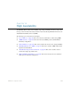
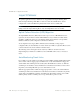
Table Of Contents
- Contents
- Figures
- Tables
- Preface
- Part 1: Basic Switching
- Accessing the Switch
- The Management Network
- Local Management Using the Console Port
- The Command Line Interface
- Remote Management Access
- Client IP Address Agents
- Securing Access to the Switch
- Setting Allowable Source IP Address Ranges
- RADIUS Authentication and Authorization
- TACACS+ Authentication
- LDAP Authentication and Authorization
- Secure Shell and Secure Copy
- Configuring SSH/SCP Features on the Switch
- Configuring the SCP Administrator Password
- Using SSH and SCP Client Commands
- SSH and SCP Encryption of Management Messages
- Generating RSA Host and Server Keys for SSH Access
- SSH/SCP Integration with Radius Authentication
- SSH/SCP Integration with TACACS+ Authentication
- End User Access Control
- Ports and Trunking
- Port-Based Network Access Control
- VLANs
- Spanning Tree Protocol
- RSTP and MSTP
- Link Layer Discovery Protocol
- Quality of Service
- Accessing the Switch
- Part 2: IP Routing
- Basic IP Routing
- Routing Information Protocol
- IGMP
- OSPF
- OSPF Overview
- OSPF Implementation in BLADE OS
- OSPF Configuration Examples
- Remote Monitoring
- Part 3: High Availability Fundamentals
- High Availability
- Layer 2 Failover
- Server Link Failure Detection
- VRRP Overview
- Failover Methods
- BLADE OS Extensions to VRRP
- Virtual Router Deployment Considerations
- High Availability Configurations
- High Availability
- Part 4: Appendices
- Index
BLADE OS 5.1 Application Guide
BMD00113, September 2009 Chapter 14: High Availability 229
VLAN Monitor
The VLAN Monitor allows Layer 2 Failover to discern different VLANs. With VLAN Monitor
turned on:
If enough links in a trigger go down (see “Setting the Failover Limit” on page 231), the switch
disables all downlink ports that reside in the same VLAN membership as the trunk(s) in the
trigger.
When enough links in the trigger return to service, the switch enables the downlink ports that
reside in the same VLAN membership as the trunk(s) in the trigger.
If you turn off the VLAN Monitor (/cfg/l2/failovr/vlan/off), only one failover trigger is
allowed. When a link failure occurs on the trigger, the switch disables all downlink ports.
Auto Monitor Configurations
Figure 27 is a simple example of Layer 2 Failover. One GbE2c is the primary, and the other is used
as a backup. In this example, all uplink ports on the primary switch belong to a single trunk group,
with Layer 2 Failover enabled, and Failover Limit set to 2. If two or fewer links in trigger 1 remain
active, the switch temporarily disables all downlink ports that reside in VLAN 1. This action causes
a failover event on Server 1 and Server 2.
Figure 27 Basic Layer 2 Failover
Internet
Internet
Enterprise
Routing Switch
Primary
Switch
Backup
Switch
Trigger 1
Blade Chassis
Server 1
Server 3
Server 2
Server 4
Trigger 1
VLAN 1:
VLAN 2:
VLAN Monitor = On
On