
BLADE OS™ Application Guide HP GbE2c Ethernet Blade Switch for c-Class BladeSystem Version 5.1 Advanced Functionality Software
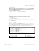
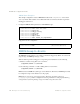


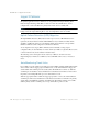
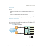
Table Of Contents
- Contents
- Figures
- Tables
- Preface
- Part 1: Basic Switching
- Accessing the Switch
- The Management Network
- Local Management Using the Console Port
- The Command Line Interface
- Remote Management Access
- Client IP Address Agents
- Securing Access to the Switch
- Setting Allowable Source IP Address Ranges
- RADIUS Authentication and Authorization
- TACACS+ Authentication
- LDAP Authentication and Authorization
- Secure Shell and Secure Copy
- Configuring SSH/SCP Features on the Switch
- Configuring the SCP Administrator Password
- Using SSH and SCP Client Commands
- SSH and SCP Encryption of Management Messages
- Generating RSA Host and Server Keys for SSH Access
- SSH/SCP Integration with Radius Authentication
- SSH/SCP Integration with TACACS+ Authentication
- End User Access Control
- Ports and Trunking
- Port-Based Network Access Control
- VLANs
- Spanning Tree Protocol
- RSTP and MSTP
- Link Layer Discovery Protocol
- Quality of Service
- Accessing the Switch
- Part 2: IP Routing
- Basic IP Routing
- Routing Information Protocol
- IGMP
- OSPF
- OSPF Overview
- OSPF Implementation in BLADE OS
- OSPF Configuration Examples
- Remote Monitoring
- Part 3: High Availability Fundamentals
- High Availability
- Layer 2 Failover
- Server Link Failure Detection
- VRRP Overview
- Failover Methods
- BLADE OS Extensions to VRRP
- Virtual Router Deployment Considerations
- High Availability Configurations
- High Availability
- Part 4: Appendices
- Index
BLADE OS 5.1 Application Guide
230 Chapter 14: High Availability BMD00113, September 2009
Figure 28 shows a configuration with two trunks, each in a different Failover Trigger. Switch 1 is
the primary GbE2c for Server 1 and Server 2. Switch 2 is the primary GbE2c for Server 3 and
Server 4. VLAN Monitor is turned on. STP is turned off.
If all links go down in trigger 1, Switch 1 disables all downlink ports that reside in VLAN 1. If all
links in trigger 2 go down, Switch 1 disables all downlink ports that reside in VLAN 2.
Figure 28 Two Trunks, with Each in a Different Failover Trigger
Figure 29 shows a configuration with two trunks. VLAN Monitor is turned off, so only one Failover
Trigger is configured on each switch. Switch 1 is the primary for Server 1 and Server 2. Switch 2 is
the primary for Server 3 and Server 4. STP is turned off.
If all links in trigger 1 go down, Switch 1 disables all internal links to server blades.
Figure 29 Two Trunks, with One Failover Trigger
Internet
Internet
Enterprise
Routing Switch
Switch 1
Switch 2
Trigger 2
Trigger 1
Trigger 1
Trigger 2
Blade Chassis
VLAN 1:
VLAN 2:
VLAN Monitor = On
On
Server 1
Server 3
Server 2
Server 4
Internet
Internet
Enterprise
Routing Switch
Switch 1
Switch 2
Trigger 1
Trigger 1
Blade Chassis
Server 1
VLAN 1:
VLAN 2:
VLAN Monitor = Off
Off
Server 3
Server 2
Server 4