
BLADE OS™ Application Guide HP GbE2c Ethernet Blade Switch for c-Class BladeSystem Version 5.1 Advanced Functionality Software
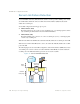
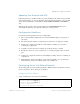
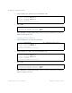
Table Of Contents
- Contents
- Figures
- Tables
- Preface
- Part 1: Basic Switching
- Accessing the Switch
- The Management Network
- Local Management Using the Console Port
- The Command Line Interface
- Remote Management Access
- Client IP Address Agents
- Securing Access to the Switch
- Setting Allowable Source IP Address Ranges
- RADIUS Authentication and Authorization
- TACACS+ Authentication
- LDAP Authentication and Authorization
- Secure Shell and Secure Copy
- Configuring SSH/SCP Features on the Switch
- Configuring the SCP Administrator Password
- Using SSH and SCP Client Commands
- SSH and SCP Encryption of Management Messages
- Generating RSA Host and Server Keys for SSH Access
- SSH/SCP Integration with Radius Authentication
- SSH/SCP Integration with TACACS+ Authentication
- End User Access Control
- Ports and Trunking
- Port-Based Network Access Control
- VLANs
- Spanning Tree Protocol
- RSTP and MSTP
- Link Layer Discovery Protocol
- Quality of Service
- Accessing the Switch
- Part 2: IP Routing
- Basic IP Routing
- Routing Information Protocol
- IGMP
- OSPF
- OSPF Overview
- OSPF Implementation in BLADE OS
- OSPF Configuration Examples
- Remote Monitoring
- Part 3: High Availability Fundamentals
- High Availability
- Layer 2 Failover
- Server Link Failure Detection
- VRRP Overview
- Failover Methods
- BLADE OS Extensions to VRRP
- Virtual Router Deployment Considerations
- High Availability Configurations
- High Availability
- Part 4: Appendices
- Index

BLADE OS 5.1 Application Guide
BMD00113, September 2009 Chapter 14: High Availability 231
Setting the Failover Limit
The failover limit lets you specify the minimum number of operational links required within each
trigger before the trigger initiates a failover event. For example, if the limit is two
(/cfg/l2/failovr/trigger <x>/limit 2), a failover event occurs when the number of
operational links in the trigger is two or fewer. When you set the limit to zero, the switch triggers a
failover event only when no links in the trigger are operational.
Manually Monitoring Port Links
The Manual Monitor allows you to configure a set of ports and/or trunks to monitor for link failures
(a monitor list), and another set of ports and/or trunks to disable when the trigger limit is reached (a
control list). When the switch detects a link failure on the monitor list, it automatically disables the
items in control list. When server ports are disabled, the corresponding server’s network adapter can
detect the disabled link, and trigger a network-adapter failover to another port or trunk on the
switch, or another switch in the chassis.
The switch automatically enables the control list items when the monitor list items return to service.
Monitor Port State
A monitor port is considered operation as long as the following conditions are true:
The port must be in the Link Up state.
If STP is enabled, the port must be in the Forwarding state.
If the port is part of an LACP trunk, the port must be in the Aggregated state.
If any of the above conditions is false, the monitor port is considered to have failed.
Control Port State
A control port is considered Operational if the monitor trigger is up. As long as the trigger is up, the
port is considered operatational from a teaming perspective, even if the port itself is actually in the
Down state, Blocking state (if STP is enabled on the port), or Not Aggregated state (if part of
an LACP trunk).
A control port is considered to have failed on if the monitor trigger is in the Down state.
To view the state of any port, use one of the following commands:
>> # /info/link (View port link status)
>> # /info/l2/stp (View port STP status)
>> # /info/l2/lacp/dump (View port LACP status)