
BLADE OS™ Application Guide HP GbE2c Ethernet Blade Switch for c-Class BladeSystem Version 5.1 Advanced Functionality Software
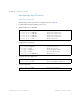
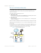
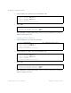
Table Of Contents
- Contents
- Figures
- Tables
- Preface
- Part 1: Basic Switching
- Accessing the Switch
- The Management Network
- Local Management Using the Console Port
- The Command Line Interface
- Remote Management Access
- Client IP Address Agents
- Securing Access to the Switch
- Setting Allowable Source IP Address Ranges
- RADIUS Authentication and Authorization
- TACACS+ Authentication
- LDAP Authentication and Authorization
- Secure Shell and Secure Copy
- Configuring SSH/SCP Features on the Switch
- Configuring the SCP Administrator Password
- Using SSH and SCP Client Commands
- SSH and SCP Encryption of Management Messages
- Generating RSA Host and Server Keys for SSH Access
- SSH/SCP Integration with Radius Authentication
- SSH/SCP Integration with TACACS+ Authentication
- End User Access Control
- Ports and Trunking
- Port-Based Network Access Control
- VLANs
- Spanning Tree Protocol
- RSTP and MSTP
- Link Layer Discovery Protocol
- Quality of Service
- Accessing the Switch
- Part 2: IP Routing
- Basic IP Routing
- Routing Information Protocol
- IGMP
- OSPF
- OSPF Overview
- OSPF Implementation in BLADE OS
- OSPF Configuration Examples
- Remote Monitoring
- Part 3: High Availability Fundamentals
- High Availability
- Layer 2 Failover
- Server Link Failure Detection
- VRRP Overview
- Failover Methods
- BLADE OS Extensions to VRRP
- Virtual Router Deployment Considerations
- High Availability Configurations
- High Availability
- Part 4: Appendices
- Index

BLADE OS 5.1 Application Guide
BMD00113, September 2009 Chapter 14: High Availability 237
Spanning Tree Protocol with SFD
If Spanning Tree Protocol (STP) is enabled on ports in the LtM, then the switch monitors the STP
state and the link status on ports in the LtM. The switch automatically enables the ports in the LtE
when it detects a link failure or when STP is in the BLOCKING, LISTENING, or LEARNING
state.
When the switch determines that ports in the LtM are in the FORWARDING State, then it
automatically disables the ports in the LtE, to fall back to normal operation.
Configuration Guidelines
Consider the following guidelines when you configure SFD:
Only one Link to Monitor (LtM) group and one Link to Enable (LtE) group is supported on
each switch.
Ports that are already members of a trunk group are not allowed to be assigned to an LtM.
A trunk group configured as an LtM can contain multiple downlink ports (1-16), but no
crosslink ports or uplink ports.
An uplink port cannot be added to a trunk group if it already belongs to an LtM.
The LtE can contain one or more crosslink ports, or one trunk group that contains crosslink
ports.
A trunk group configured as an LtE can contain multiple crosslink ports, but no downlink ports
or uplink ports.
LACP admin keys added to the LtM may not be shared with uplink ports or crosslink ports.
LACP admin keys added to the LtE may include only crosslink ports.
Configuring Server Link Failure Detection
The preceding figure shows a basic SFD configuration. Traffic intended for the Internet is routed to
Server 1 and Server 2. The crosslink ports are disabled.
Configuring SFD on Switch 1
1. Assign downlink ports to be monitored for link failure.
>> Main# /cfg/sfd/ltm (Select SFD Link to Monitor menu)
>> Link to Monitor# addport 1
>> Link to Monitor# addport 2
>> Link to Monitor# ..
>> Server Link Failure Detection#