
BLADE OS™ Application Guide HP GbE2c Ethernet Blade Switch for c-Class BladeSystem Version 5.1 Advanced Functionality Software
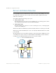
Table Of Contents
- Contents
- Figures
- Tables
- Preface
- Part 1: Basic Switching
- Accessing the Switch
- The Management Network
- Local Management Using the Console Port
- The Command Line Interface
- Remote Management Access
- Client IP Address Agents
- Securing Access to the Switch
- Setting Allowable Source IP Address Ranges
- RADIUS Authentication and Authorization
- TACACS+ Authentication
- LDAP Authentication and Authorization
- Secure Shell and Secure Copy
- Configuring SSH/SCP Features on the Switch
- Configuring the SCP Administrator Password
- Using SSH and SCP Client Commands
- SSH and SCP Encryption of Management Messages
- Generating RSA Host and Server Keys for SSH Access
- SSH/SCP Integration with Radius Authentication
- SSH/SCP Integration with TACACS+ Authentication
- End User Access Control
- Ports and Trunking
- Port-Based Network Access Control
- VLANs
- Spanning Tree Protocol
- RSTP and MSTP
- Link Layer Discovery Protocol
- Quality of Service
- Accessing the Switch
- Part 2: IP Routing
- Basic IP Routing
- Routing Information Protocol
- IGMP
- OSPF
- OSPF Overview
- OSPF Implementation in BLADE OS
- OSPF Configuration Examples
- Remote Monitoring
- Part 3: High Availability Fundamentals
- High Availability
- Layer 2 Failover
- Server Link Failure Detection
- VRRP Overview
- Failover Methods
- BLADE OS Extensions to VRRP
- Virtual Router Deployment Considerations
- High Availability Configurations
- High Availability
- Part 4: Appendices
- Index

BLADE OS 5.1 Application Guide
240 Chapter 14: High Availability BMD00113, September 2009
Master and Backup Virtual Router
Within each virtual router, one VRRP router is selected to be the virtual router master. See
“Selecting the Master VRRP Router” on page 241 for an explanation of the selection process.
Note – If the IP address owner is available, it will always become the virtual router master.
The virtual router master forwards packets sent to the virtual router. It also responds to Address
Resolution Protocol (ARP) requests sent to the virtual router's IP address. Finally, the virtual router
master sends out periodic advertisements to let other VRRP routers know it is alive and its priority.
Within a virtual router, the VRRP routers not selected to be the master are known as virtual router
backups. Should the virtual router master fail, one of the virtual router backups becomes the master
and assumes its responsibilities.
Virtual Interface Router
At Layer 3, a Virtual Interface Router (VIR) allows two VRRP routers to share an IP interface
across the routers. VIRs provide a single Destination IP (DIP) for upstream routers to reach various
destination networks, and provide a virtual default Gateway.
Note – Every VIR must be assigned to an IP interface, and every IP interface must be assigned to
a VLAN. If no port in a VLAN has link up, the IP interface of that VLAN is down, and if the IP
interface of a VIR is down, that VIR goes into INIT state.
VRRP Operation
Only the virtual router master responds to ARP requests. Therefore, the upstream routers only
forward packets destined to the master. The master also responds to ICMP ping requests. The
backup does not forward any traffic, nor does it respond to ARP requests.
If the master is not available, the backup becomes the master and takes over responsibility for
packet forwarding and responding to ARP requests.