
BLADE OS™ Application Guide HP GbE2c Ethernet Blade Switch for c-Class BladeSystem Version 5.1 Advanced Functionality Software
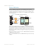
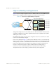

Table Of Contents
- Contents
- Figures
- Tables
- Preface
- Part 1: Basic Switching
- Accessing the Switch
- The Management Network
- Local Management Using the Console Port
- The Command Line Interface
- Remote Management Access
- Client IP Address Agents
- Securing Access to the Switch
- Setting Allowable Source IP Address Ranges
- RADIUS Authentication and Authorization
- TACACS+ Authentication
- LDAP Authentication and Authorization
- Secure Shell and Secure Copy
- Configuring SSH/SCP Features on the Switch
- Configuring the SCP Administrator Password
- Using SSH and SCP Client Commands
- SSH and SCP Encryption of Management Messages
- Generating RSA Host and Server Keys for SSH Access
- SSH/SCP Integration with Radius Authentication
- SSH/SCP Integration with TACACS+ Authentication
- End User Access Control
- Ports and Trunking
- Port-Based Network Access Control
- VLANs
- Spanning Tree Protocol
- RSTP and MSTP
- Link Layer Discovery Protocol
- Quality of Service
- Accessing the Switch
- Part 2: IP Routing
- Basic IP Routing
- Routing Information Protocol
- IGMP
- OSPF
- OSPF Overview
- OSPF Implementation in BLADE OS
- OSPF Configuration Examples
- Remote Monitoring
- Part 3: High Availability Fundamentals
- High Availability
- Layer 2 Failover
- Server Link Failure Detection
- VRRP Overview
- Failover Methods
- BLADE OS Extensions to VRRP
- Virtual Router Deployment Considerations
- High Availability Configurations
- High Availability
- Part 4: Appendices
- Index
BLADE OS 5.1 Application Guide
BMD00113, September 2009 Chapter 14: High Availability 243
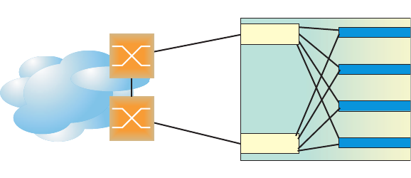
Active-Active Redundancy
In an active-active configuration, shown in Figure 32, two switches provide redundancy for each
other, with both active at the same time. Each switch processes traffic on a different subnet. When a
failure occurs, the remaining switch can process traffic on all subnets.
For a configuration example, see “High Availability Configurations” on page 246.
Figure 32 Active-Active Redundancy
Virtual Router Group
The virtual router group ties all virtual routers on the switch together as a single entity. As members
of a group, all virtual routers on the switch (and therefore the switch itself), are in either a master or
standby state.
The virtual router group cannot be used for active-active configurations or any other configuration
that require shared interfaces.
A VRRP group has the following characteristics:
When enabled, all virtual routers behave as one entity, and all group settings override any
individual virtual router settings.
All individual virtual routers, once the VRRP group is enabled, assume the group’s tracking
and priority.
When one member of a VRRP group fails, the priority of the group decreases, and the state of
the entire switch changes from Master to Standby.
Each VRRP advertisement can include up to 128 addresses. All virtual routers are advertised within
the same packet, conserving processing and buffering resources.
Internet
Internet
Enterprise
Routing Switch
Switch A
Switch B
Servers
Active (subnet A and C)
Active (subnet B and D)