
BLADE OS™ Application Guide HP GbE2c Ethernet Blade Switch for c-Class BladeSystem Version 5.1 Advanced Functionality Software
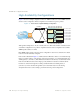

Table Of Contents
- Contents
- Figures
- Tables
- Preface
- Part 1: Basic Switching
- Accessing the Switch
- The Management Network
- Local Management Using the Console Port
- The Command Line Interface
- Remote Management Access
- Client IP Address Agents
- Securing Access to the Switch
- Setting Allowable Source IP Address Ranges
- RADIUS Authentication and Authorization
- TACACS+ Authentication
- LDAP Authentication and Authorization
- Secure Shell and Secure Copy
- Configuring SSH/SCP Features on the Switch
- Configuring the SCP Administrator Password
- Using SSH and SCP Client Commands
- SSH and SCP Encryption of Management Messages
- Generating RSA Host and Server Keys for SSH Access
- SSH/SCP Integration with Radius Authentication
- SSH/SCP Integration with TACACS+ Authentication
- End User Access Control
- Ports and Trunking
- Port-Based Network Access Control
- VLANs
- Spanning Tree Protocol
- RSTP and MSTP
- Link Layer Discovery Protocol
- Quality of Service
- Accessing the Switch
- Part 2: IP Routing
- Basic IP Routing
- Routing Information Protocol
- IGMP
- OSPF
- OSPF Overview
- OSPF Implementation in BLADE OS
- OSPF Configuration Examples
- Remote Monitoring
- Part 3: High Availability Fundamentals
- High Availability
- Layer 2 Failover
- Server Link Failure Detection
- VRRP Overview
- Failover Methods
- BLADE OS Extensions to VRRP
- Virtual Router Deployment Considerations
- High Availability Configurations
- High Availability
- Part 4: Appendices
- Index

BLADE OS 5.1 Application Guide
BMD00113, September 2009 Chapter 14: High Availability 245
Virtual Router Deployment Considerations
Assigning VRRP Virtual Router ID
During the software upgrade process, VRRP virtual router IDs will be automatically assigned if
failover is enabled on the switch. When configuring virtual routers at any point after upgrade,
virtual router ID numbers (/cfg/l3/vrrp/vr
#/vrid) must be assigned. The virtual router ID
may be configured as any number between 1 and 255.
Configuring the Switch for Tracking
Tracking configuration largely depends on user preferences and network environment. Consider the
configuration shown in Figure 32 on page 243. Assume the following behavior on the network:
Switch 1 is the master router upon initialization.
If switch 1 is the master and it has one fewer active servers than switch 2, then switch 1 remains
the master.
This behavior is preferred because running one server down is less disruptive than bringing a
new master online and severing all active connections in the process.
If switch 1 is the master and it has two or more active servers fewer than switch 2, then switch
2 becomes the master.
If switch 2 is the master, it remains the master even if servers are restored on switch 1 such that
it has one fewer or an equal number of servers.
If switch 2 is the master and it has one active server fewer than switch 1, then switch 1 becomes
the master.
The user can implement this behavior by configuring the switch for tracking as follows:
1. Set the priority for switch 1 to 101.
2. Leave the priority for switch 2 at the default value of 100.
3. On both switches, enable tracking based on ports (ports), interfaces (ifs), or virtual routers
(vr). You can choose any combination of tracking parameters, based on your network
configuration.
Note – There is no shortcut to setting tracking parameters. The goals must first be set and the
outcomes of various configurations and scenarios analyzed to find settings that meet the goals.