
BLADE OS™ Application Guide HP GbE2c Ethernet Blade Switch for c-Class BladeSystem Version 5.1 Advanced Functionality Software
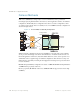
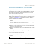


Table Of Contents
- Contents
- Figures
- Tables
- Preface
- Part 1: Basic Switching
- Accessing the Switch
- The Management Network
- Local Management Using the Console Port
- The Command Line Interface
- Remote Management Access
- Client IP Address Agents
- Securing Access to the Switch
- Setting Allowable Source IP Address Ranges
- RADIUS Authentication and Authorization
- TACACS+ Authentication
- LDAP Authentication and Authorization
- Secure Shell and Secure Copy
- Configuring SSH/SCP Features on the Switch
- Configuring the SCP Administrator Password
- Using SSH and SCP Client Commands
- SSH and SCP Encryption of Management Messages
- Generating RSA Host and Server Keys for SSH Access
- SSH/SCP Integration with Radius Authentication
- SSH/SCP Integration with TACACS+ Authentication
- End User Access Control
- Ports and Trunking
- Port-Based Network Access Control
- VLANs
- Spanning Tree Protocol
- RSTP and MSTP
- Link Layer Discovery Protocol
- Quality of Service
- Accessing the Switch
- Part 2: IP Routing
- Basic IP Routing
- Routing Information Protocol
- IGMP
- OSPF
- OSPF Overview
- OSPF Implementation in BLADE OS
- OSPF Configuration Examples
- Remote Monitoring
- Part 3: High Availability Fundamentals
- High Availability
- Layer 2 Failover
- Server Link Failure Detection
- VRRP Overview
- Failover Methods
- BLADE OS Extensions to VRRP
- Virtual Router Deployment Considerations
- High Availability Configurations
- High Availability
- Part 4: Appendices
- Index
BLADE OS 5.1 Application Guide
246 Chapter 14: High Availability BMD00113, September 2009
High Availability Configurations
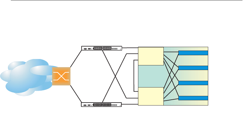
Figure 33 shows an example configuration where two GbE2c modules are used as VRRP routers in
an active-active configuration. In this configuration, both switches respond to packets.
Figure 33 Active-Active High-Availability Configuration
Although this example shows only two switches, there is no limit on the number of switches used in
a redundant configuration. It is possible to implement an active-active configuration across all the
VRRP-capable switches in a LAN.
Each VRRP-capable switch in an active-active configuration is autonomous. Switches in a virtual
router need not be identically configured.
In the scenario illustrated in Figure 33, traffic destined for IP address 10.0.1.1 is forwarded through
the Layer 2 switch at the top of the drawing, and ingresses Switch A on port 20. Return traffic uses
default gateway 1 (192.168.1.1). If the link between Switch A and the Layer 2 switch fails, Switch
B becomes the Master because it has a higher priority. Traffic is forwarded to Switch B, which
forwards it to Switch A through the crosslink port. Return traffic uses default gateway 2
(192.168.2.1), and is forwarded through the Layer 2 switch at the bottom of the drawing.
To implement the active-active example, perform the following switch configuration.
Internet
Internet
Enterprise
Routing Switch
Server 1
VIR 1: 192.168.1.200 (Master)
VIR 2: 192.168.2.200 (Backup)
VIR 1: 192.168.1.200 (Backup)
VIR 2: 192.168.2.200 (Master)
NIC 1: 10.0.1.1/24
NIC 2: 10.0.2.1/24
NIC 1: 10.0.1.2/24
NIC 2: 10.0.2.2/24
NIC 1: 10.0.1.3/24
NIC 2: 10.0.2.3/24
NIC 1: 10.0.1.4/24
NIC 2: 10.0.2.4/24
Server 2
Server 3
Server 4
L2 Switch
L2 Switch
20
21
20
21
Switch A
Switch B