
BLADE OS™ Application Guide HP GbE2c Ethernet Blade Switch for c-Class BladeSystem Version 5.1 Advanced Functionality Software
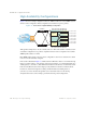

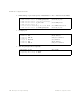
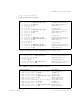
Table Of Contents
- Contents
- Figures
- Tables
- Preface
- Part 1: Basic Switching
- Accessing the Switch
- The Management Network
- Local Management Using the Console Port
- The Command Line Interface
- Remote Management Access
- Client IP Address Agents
- Securing Access to the Switch
- Setting Allowable Source IP Address Ranges
- RADIUS Authentication and Authorization
- TACACS+ Authentication
- LDAP Authentication and Authorization
- Secure Shell and Secure Copy
- Configuring SSH/SCP Features on the Switch
- Configuring the SCP Administrator Password
- Using SSH and SCP Client Commands
- SSH and SCP Encryption of Management Messages
- Generating RSA Host and Server Keys for SSH Access
- SSH/SCP Integration with Radius Authentication
- SSH/SCP Integration with TACACS+ Authentication
- End User Access Control
- Ports and Trunking
- Port-Based Network Access Control
- VLANs
- Spanning Tree Protocol
- RSTP and MSTP
- Link Layer Discovery Protocol
- Quality of Service
- Accessing the Switch
- Part 2: IP Routing
- Basic IP Routing
- Routing Information Protocol
- IGMP
- OSPF
- OSPF Overview
- OSPF Implementation in BLADE OS
- OSPF Configuration Examples
- Remote Monitoring
- Part 3: High Availability Fundamentals
- High Availability
- Layer 2 Failover
- Server Link Failure Detection
- VRRP Overview
- Failover Methods
- BLADE OS Extensions to VRRP
- Virtual Router Deployment Considerations
- High Availability Configurations
- High Availability
- Part 4: Appendices
- Index

BLADE OS 5.1 Application Guide
BMD00113, September 2009 Chapter 14: High Availability 249
Task 2: Configure Switch B
1. Configure client and server interfaces.
2. Configure the default gateways. Each default gateway points to a Layer 3 router.
3. Turn on VRRP and configure two Virtual Interface Routers.
/cfg/l3/if 1 (Select interface 1)
>> IP Interface 1# addr 192.168.1.101 (Define IP address for interface 1)
>> IP Interface 1# vlan 10 (Assign VLAN 10 to interface 1)
>> IP Interface 1# ena (Enable interface 1)
>> IP Interface 1# ..
>> Layer 3# if 2 (Select interface 2)
>> IP Interface 2# addr 192.168.2.100 (Define IP address for interface 2)
>> IP Interface 2# vlan 20 (Assign VLAN 20 to interface 2)
>> IP Interface 2# ena (Enable interface 2)
>> IP Interface 2# ..
>> Layer 3# if 3 (Select interface 3)
>> IP Interface 3# addr 10.0.1.101 (Define IP address for interface 3)
>> IP Interface 3# mask 255.255.255.0 (Define subnet mask for interface 3)
>> IP Interface 3# ena (Enable interface 3)
>> IP Interface 3# ..
>> Layer 3# if 4 (Select interface 4)
>> IP Interface 4# addr 10.0.2.100 (Define IP address for interface 4)
>> IP Interface 4# mask 255.255.255.0 (Define subnet mask for interface 4)
>> IP Interface 4# ena (Enable interface 4)
/cfg/l3/gw 1 (Select default gateway 1)
>> Default gateway 1# addr 192.168.2.1 (Point gateway to the first L3 router)
>> Default gateway 1# ena (Enable the default gateway)
>> Default gateway 1# ..
>> Layer 3# gw 2 (Select default gateway 2)
>> Default gateway 2# addr 192.168.1.1 (Point gateway to the second router)
>> Default gateway 2# ena (Enable the default gateway)
/cfg/l3/vrrp/on (Turn VRRP on)
>> Virtual Router Redundancy Protocol# vr 1 (Select virtual router 1)
>> VRRP Virtual Router 1# vrid 1 (Set VRID to 1)
>> VRRP Virtual Router 1# if 1 (Set interface 1)
>> VRRP Virtual Router 1# addr 192.168.1.200 (Define IP address)
>> VRRP Virtual Router 1# ena (Enable virtual router 1)
>> VRRP Virtual Router 1# .. (Enable virtual router 1)
>> Virtual Router Redundancy Protocol# vr 2 (Select virtual router 2)
>> VRRP Virtual Router 2# vrid 2 (Set VRID to 2)
>> VRRP Virtual Router 2# if 2 (Set interface 2)
>> VRRP Virtual Router 2# addr 192.168.2.200 (Define IP address)
>> VRRP Virtual Router 2# ena (Enable virtual router 2)