
BLADE OS™ Application Guide HP GbE2c Ethernet Blade Switch for c-Class BladeSystem Version 5.1 Advanced Functionality Software

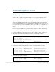
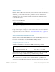
Table Of Contents
- Contents
- Figures
- Tables
- Preface
- Part 1: Basic Switching
- Accessing the Switch
- The Management Network
- Local Management Using the Console Port
- The Command Line Interface
- Remote Management Access
- Client IP Address Agents
- Securing Access to the Switch
- Setting Allowable Source IP Address Ranges
- RADIUS Authentication and Authorization
- TACACS+ Authentication
- LDAP Authentication and Authorization
- Secure Shell and Secure Copy
- Configuring SSH/SCP Features on the Switch
- Configuring the SCP Administrator Password
- Using SSH and SCP Client Commands
- SSH and SCP Encryption of Management Messages
- Generating RSA Host and Server Keys for SSH Access
- SSH/SCP Integration with Radius Authentication
- SSH/SCP Integration with TACACS+ Authentication
- End User Access Control
- Ports and Trunking
- Port-Based Network Access Control
- VLANs
- Spanning Tree Protocol
- RSTP and MSTP
- Link Layer Discovery Protocol
- Quality of Service
- Accessing the Switch
- Part 2: IP Routing
- Basic IP Routing
- Routing Information Protocol
- IGMP
- OSPF
- OSPF Overview
- OSPF Implementation in BLADE OS
- OSPF Configuration Examples
- Remote Monitoring
- Part 3: High Availability Fundamentals
- High Availability
- Layer 2 Failover
- Server Link Failure Detection
- VRRP Overview
- Failover Methods
- BLADE OS Extensions to VRRP
- Virtual Router Deployment Considerations
- High Availability Configurations
- High Availability
- Part 4: Appendices
- Index

BLADE OS 5.1 Application Guide
26 Chapter 1: Accessing the Switch BMD00113, September 2009
Remote Management Access
Configuring an IP Interface
An IP interface address must be set on the switch to provide management access to the switch over
an IP network. By default, the management interface is set up to request its IP address from a
Bootstrap Protocol (BOOTP) server.
If you have a BOOTP server on your network, add the Media Access Control (MAC) address of the
switch to the BOOTP configuration file located on the BOOTP server. The MAC address can be
found on a small white label on the back panel of the switch. The MAC address can also be found
in the System Information menu (see the BLADE OS 5.1 Command Reference or ISCLI Reference.)
If you are using a DHCP server that also does BOOTP, you do not have to configure the MAC
address.
If you do not have a BOOTP server, you must manually configure an IP address. The following
example shows how to manually configure an IP address on the switch:
1. Configure an IP interface for the Telnet connection, using the sample IP address of 205.21.17.3.
2. The pending subnet mask address and broadcast address are automatically calculated.
3. If necessary, configure up to two default gateways.
4. Configuring the default gateways allows the switch to send outbound traffic to the routers.
5. Apply, verify, and save the configuration.
>> # /cfg/l3/if 1 (Select IP interface 1)
>> IP Interface 1# addr 205.21.17.3 (Assign IP address for the interface)
Current IP address: 0.0.0.0
New pending IP address: 205.21.17.3
Pending new subnet mask: 255.255.255.0
>> IP Interface 1# ena (Enable IP interface 1)
>> IP Interface 5# ../gw 1 (Select primary default gateway)
>> Default gateway 1# addr 205.21.17.1 (Assign IP address for primary router)
>> Default gateway 1# ena (Enable primary default gateway)
>> Default gateway 1# ../gw 2 (Select secondary default gateway)
>> Default gateway 2# addr 205.21.17.2 (Assign address for secondary router)
>> Default gateway 2# ena (Enable secondary default gateway)
>> Default gateway 2# apply (Apply the configuration)
>> Default gateway 2# save (Save the configuration)
>> # /cfg/dump (Verify the configuration)