
BLADE OS™ Application Guide HP GbE2c Ethernet Blade Switch for c-Class BladeSystem Version 5.1 Advanced Functionality Software

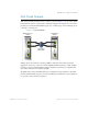

Table Of Contents
- Contents
- Figures
- Tables
- Preface
- Part 1: Basic Switching
- Accessing the Switch
- The Management Network
- Local Management Using the Console Port
- The Command Line Interface
- Remote Management Access
- Client IP Address Agents
- Securing Access to the Switch
- Setting Allowable Source IP Address Ranges
- RADIUS Authentication and Authorization
- TACACS+ Authentication
- LDAP Authentication and Authorization
- Secure Shell and Secure Copy
- Configuring SSH/SCP Features on the Switch
- Configuring the SCP Administrator Password
- Using SSH and SCP Client Commands
- SSH and SCP Encryption of Management Messages
- Generating RSA Host and Server Keys for SSH Access
- SSH/SCP Integration with Radius Authentication
- SSH/SCP Integration with TACACS+ Authentication
- End User Access Control
- Ports and Trunking
- Port-Based Network Access Control
- VLANs
- Spanning Tree Protocol
- RSTP and MSTP
- Link Layer Discovery Protocol
- Quality of Service
- Accessing the Switch
- Part 2: IP Routing
- Basic IP Routing
- Routing Information Protocol
- IGMP
- OSPF
- OSPF Overview
- OSPF Implementation in BLADE OS
- OSPF Configuration Examples
- Remote Monitoring
- Part 3: High Availability Fundamentals
- High Availability
- Layer 2 Failover
- Server Link Failure Detection
- VRRP Overview
- Failover Methods
- BLADE OS Extensions to VRRP
- Virtual Router Deployment Considerations
- High Availability Configurations
- High Availability
- Part 4: Appendices
- Index
BLADE OS 5.1 Application Guide
68 Chapter 2: Ports and Trunking BMD00113, September 2009
Statistical Load Distribution
In a configured trunk group containing more than one port, the load distribution is determined by
information embedded within the data frame.
For IP traffic, distribution is based on IP addresses. The switch calculates the trunk port to use for
forwarding traffic by implementing a load distribution algorithm based on the following:
modulus ( <last 3 bits of Source IP address> XOR <last 3 bits of Destination IP address> )
For IP traffic, distribution is based on MAC addresses. For non-IP traffic, the switch will calculate
the trunk port to use for forwarding traffic by implementing the load distribution algorithm based
on: the following:
modulus ( <last 3 bits of Source MAC address> XOR <last 3 bits of Destination MAC address> )
Each packet’s particular combination of source and destination addresses results in selecting one
line in the trunk group for data transmission. With a greater number of devices contributing traffic
to the trunk lines, the traffic distribution becomes more statistically even.
Built-In Fault Tolerance
Since each trunk group is comprised of multiple physical links, the trunk group is inherently fault
tolerant. As long as one connection between the switches is available, the trunk remains active.
Statistical load balancing is maintained whenever a port in a trunk group is lost or returned to service.
Before You Configure Static Trunks
When you create and enable a static trunk, the trunk members (switch ports) take on certain settings
necessary for correct operation of the trunking feature.
Before you configure your trunk, you must consider these settings, along with specific
configuration rules, as follows:
1. Read the configuration rules provided in the section, “Trunk Group Configuration Rules” on page 69.”
2. Determine which switch ports are to become trunk members (the specific ports making up the
trunk). Up to 8 member ports are supported for each trunk.
3. Ensure that the chosen switch ports are set to enabled. Use the /cfg/port <port>/cur
command to view port settings.
4. Trunk member ports must have the same VLAN configuration.
5. Consider how the existing Spanning Tree will react to the new trunk configuration. See “Spanning
Tree Protocol” on page 109” for Spanning Tree Group configuration guidelines.
6. Consider how existing VLANs will be affected by the addition of a trunk.