
BLADE OS™ Application Guide HP GbE2c Ethernet Blade Switch for c-Class BladeSystem Version 5.1 Advanced Functionality Software

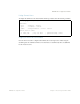

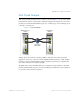

Table Of Contents
- Contents
- Figures
- Tables
- Preface
- Part 1: Basic Switching
- Accessing the Switch
- The Management Network
- Local Management Using the Console Port
- The Command Line Interface
- Remote Management Access
- Client IP Address Agents
- Securing Access to the Switch
- Setting Allowable Source IP Address Ranges
- RADIUS Authentication and Authorization
- TACACS+ Authentication
- LDAP Authentication and Authorization
- Secure Shell and Secure Copy
- Configuring SSH/SCP Features on the Switch
- Configuring the SCP Administrator Password
- Using SSH and SCP Client Commands
- SSH and SCP Encryption of Management Messages
- Generating RSA Host and Server Keys for SSH Access
- SSH/SCP Integration with Radius Authentication
- SSH/SCP Integration with TACACS+ Authentication
- End User Access Control
- Ports and Trunking
- Port-Based Network Access Control
- VLANs
- Spanning Tree Protocol
- RSTP and MSTP
- Link Layer Discovery Protocol
- Quality of Service
- Accessing the Switch
- Part 2: IP Routing
- Basic IP Routing
- Routing Information Protocol
- IGMP
- OSPF
- OSPF Overview
- OSPF Implementation in BLADE OS
- OSPF Configuration Examples
- Remote Monitoring
- Part 3: High Availability Fundamentals
- High Availability
- Layer 2 Failover
- Server Link Failure Detection
- VRRP Overview
- Failover Methods
- BLADE OS Extensions to VRRP
- Virtual Router Deployment Considerations
- High Availability Configurations
- High Availability
- Part 4: Appendices
- Index
BLADE OS 5.1 Application Guide
BMD00113, September 2009 Chapter 2: Ports and Trunking 69
Trunk Group Configuration Rules
The trunking feature operates according to specific configuration rules. When creating trunks,
consider the following rules that determine how a trunk group reacts in any network topology:
All trunks must originate from one device, and lead to one destination device. For example,
you cannot combine a link from Server 1 and a link from Server 2, into one trunk group.
Any physical switch port can belong to only one trunk group.
Downlink ports and uplink ports cannot become members of the same trunk group.
Trunking from third-party devices must comply with Cisco
®
EtherChannel
®
technology.
All trunk member ports must be assigned to the same VLAN configuration before the trunk can
be enabled.
If you change the VLAN settings of any trunk member, you cannot apply the change until you
change the VLAN settings of all trunk members.
When an active port is configured in a trunk, the port becomes a trunk member when you
enable the trunk using the following command:
/cfg/l2/trunk <x>/ena
The Spanning Tree parameters for the port then change to reflect the new trunk settings.
All trunk members must be in the same Spanning Tree Group (STG) and can belong to only
one Spanning Tree Group (STG). However if all ports are tagged, then all trunk ports can
belong to multiple STGs.
If you change the Spanning Tree participation of any trunk member to enabled or
disabled, the Spanning Tree participation of all members of that trunk changes similarly.
When a trunk is enabled, the trunk Spanning Tree participation setting takes precedence over
that of any trunk member.
You cannot configure a trunk member as a monitor port in a port-mirroring configuration.
Trunks cannot be monitored by a monitor port; however, trunk members can be monitored.
All ports in static trunks must be have the same link configuration (speed, duplex, flow
control).