
BLADE OS™ Application Guide HP GbE2c Ethernet Blade Switch for c-Class BladeSystem Version 5.1 Advanced Functionality Software

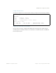

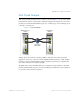

Table Of Contents
- Contents
- Figures
- Tables
- Preface
- Part 1: Basic Switching
- Accessing the Switch
- The Management Network
- Local Management Using the Console Port
- The Command Line Interface
- Remote Management Access
- Client IP Address Agents
- Securing Access to the Switch
- Setting Allowable Source IP Address Ranges
- RADIUS Authentication and Authorization
- TACACS+ Authentication
- LDAP Authentication and Authorization
- Secure Shell and Secure Copy
- Configuring SSH/SCP Features on the Switch
- Configuring the SCP Administrator Password
- Using SSH and SCP Client Commands
- SSH and SCP Encryption of Management Messages
- Generating RSA Host and Server Keys for SSH Access
- SSH/SCP Integration with Radius Authentication
- SSH/SCP Integration with TACACS+ Authentication
- End User Access Control
- Ports and Trunking
- Port-Based Network Access Control
- VLANs
- Spanning Tree Protocol
- RSTP and MSTP
- Link Layer Discovery Protocol
- Quality of Service
- Accessing the Switch
- Part 2: IP Routing
- Basic IP Routing
- Routing Information Protocol
- IGMP
- OSPF
- OSPF Overview
- OSPF Implementation in BLADE OS
- OSPF Configuration Examples
- Remote Monitoring
- Part 3: High Availability Fundamentals
- High Availability
- Layer 2 Failover
- Server Link Failure Detection
- VRRP Overview
- Failover Methods
- BLADE OS Extensions to VRRP
- Virtual Router Deployment Considerations
- High Availability Configurations
- High Availability
- Part 4: Appendices
- Index
BLADE OS 5.1 Application Guide
70 Chapter 2: Ports and Trunking BMD00113, September 2009
Port Trunking Example
In this example, the uplink ports and the crosslink ports on each switch are configured into a total of
five trunk groups: two on each switch, and one trunk group at the crosslink between the two
switches.
Note – The actual mapping of switch ports to NIC interfaces is dependant on the operating system
software, the type of server blade, and the enclosure type. For more information, see the HP GbE2c
Ethernet Blade Switch User Guide.
Figure 4 Port Trunk Group Configuration Example
123
4
Server 1
123
4
Server 2
123
4
Server 3
123
4
Server 4
123
4
Server 5
123
4
Server 6
123
4
Server 7
123
4
Server 8
Backplane
Switch 2Switch 1
1
2
3
4
5
6
7
8
9
10
11
12
13
14
15
16
1
2
3
4
5
6
7
8
9
10
1
1
12
13
14
15
16
24 23 22 21 20
2423222120
Gigabit Uplinks
(front)
Trunk
Group 5
1818
1717
10/100/1000
Inter-switch
Links
Trunk Group 2
Trunk Group 4Trunk Group 3
Trunk Group 1
Internet