
BLADE OS™ Application Guide HP GbE2c Ethernet Blade Switch for c-Class BladeSystem Version 5.1 Advanced Functionality Software
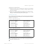


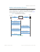
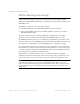
Table Of Contents
- Contents
- Figures
- Tables
- Preface
- Part 1: Basic Switching
- Accessing the Switch
- The Management Network
- Local Management Using the Console Port
- The Command Line Interface
- Remote Management Access
- Client IP Address Agents
- Securing Access to the Switch
- Setting Allowable Source IP Address Ranges
- RADIUS Authentication and Authorization
- TACACS+ Authentication
- LDAP Authentication and Authorization
- Secure Shell and Secure Copy
- Configuring SSH/SCP Features on the Switch
- Configuring the SCP Administrator Password
- Using SSH and SCP Client Commands
- SSH and SCP Encryption of Management Messages
- Generating RSA Host and Server Keys for SSH Access
- SSH/SCP Integration with Radius Authentication
- SSH/SCP Integration with TACACS+ Authentication
- End User Access Control
- Ports and Trunking
- Port-Based Network Access Control
- VLANs
- Spanning Tree Protocol
- RSTP and MSTP
- Link Layer Discovery Protocol
- Quality of Service
- Accessing the Switch
- Part 2: IP Routing
- Basic IP Routing
- Routing Information Protocol
- IGMP
- OSPF
- OSPF Overview
- OSPF Implementation in BLADE OS
- OSPF Configuration Examples
- Remote Monitoring
- Part 3: High Availability Fundamentals
- High Availability
- Layer 2 Failover
- Server Link Failure Detection
- VRRP Overview
- Failover Methods
- BLADE OS Extensions to VRRP
- Virtual Router Deployment Considerations
- High Availability Configurations
- High Availability
- Part 4: Appendices
- Index

BLADE OS 5.1 Application Guide
BMD00113, September 2009 Chapter 2: Ports and Trunking 71
The trunk groups are configured as follows:
Trunk groups 1 through 4 consist of two uplink ports each, configured to act as a single link to
the upstream routers. The trunk groups on each switch are configured so that there is a link to
each router for redundancy.
Trunk group 5 is configured by default on the crosslink ports 17 and 18, which connect the
switches 1 and 2 together. Since this is the default configuration, you do not need to configure
trunk group 1 on either switch. By default, ports 17 and 18 are disabled.
Configuring Trunk Groups
Prior to configuring each switch in this example, you must connect to the appropriate switch CLI as the
administrator. For details about accessing and using any of the commands described in this example,
BLADE OS 5.1 Command Reference.
1. On Switch 1, configure trunk groups 1 and 3:
2. On Switch 2, configure trunk groups 2 and 4:
Note – In this example, two switches are used. Any third-party device supporting link aggregation
should be configured manually. Connection problems could arise when using automatic trunk
group negotiation on the third-party device.
>> # /cfg/l2/trunk 1 (Select trunk group 1)
>> Trunk group 1# add 20 (Add port 20 to trunk group 1)
>> Trunk group 1# add 21 (Add port 21 to trunk group 1)
>> Trunk group 1# ena (Enable trunk group 1)
>> # /cfg/l2/trunk 3 (Select trunk group 3)
>> Trunk group 3# add 23 (Add port 23 to trunk group 3)
>> Trunk group 3# add 24 (Add port 24 to trunk group 3)
>> Trunk group 3# ena (Enable trunk group 3)
>> Trunk group 3# apply (Make your changes active)
>> Trunk group 3# save (Save for restore after reboot)
>> # /cfg/l2/trunk 2 (Select trunk group 2)
>> Trunk group 2# add 20 (Add port 20 to trunk group 2)
>> Trunk group 2# add 21 (Add port 21 to trunk group 2)
>> Trunk group 2# ena (Enable trunk group 2)
>> # /cfg/l2/trunk 4 (Select trunk group 4)
>> Trunk group 4# add 23 (Add port 23 to trunk group 4)
>> Trunk group 4# add 24 (Add port 24 to trunk group 4)
>> Trunk group 4# ena (Enable trunk group 4)
>> Trunk group 4# apply (Make your changes active)
>> Trunk group 4# save (Save for restore after reboot)