
BLADE OS™ Application Guide HP GbE2c Ethernet Blade Switch for c-Class BladeSystem Version 5.1 Advanced Functionality Software
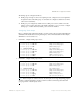


Table Of Contents
- Contents
- Figures
- Tables
- Preface
- Part 1: Basic Switching
- Accessing the Switch
- The Management Network
- Local Management Using the Console Port
- The Command Line Interface
- Remote Management Access
- Client IP Address Agents
- Securing Access to the Switch
- Setting Allowable Source IP Address Ranges
- RADIUS Authentication and Authorization
- TACACS+ Authentication
- LDAP Authentication and Authorization
- Secure Shell and Secure Copy
- Configuring SSH/SCP Features on the Switch
- Configuring the SCP Administrator Password
- Using SSH and SCP Client Commands
- SSH and SCP Encryption of Management Messages
- Generating RSA Host and Server Keys for SSH Access
- SSH/SCP Integration with Radius Authentication
- SSH/SCP Integration with TACACS+ Authentication
- End User Access Control
- Ports and Trunking
- Port-Based Network Access Control
- VLANs
- Spanning Tree Protocol
- RSTP and MSTP
- Link Layer Discovery Protocol
- Quality of Service
- Accessing the Switch
- Part 2: IP Routing
- Basic IP Routing
- Routing Information Protocol
- IGMP
- OSPF
- OSPF Overview
- OSPF Implementation in BLADE OS
- OSPF Configuration Examples
- Remote Monitoring
- Part 3: High Availability Fundamentals
- High Availability
- Layer 2 Failover
- Server Link Failure Detection
- VRRP Overview
- Failover Methods
- BLADE OS Extensions to VRRP
- Virtual Router Deployment Considerations
- High Availability Configurations
- High Availability
- Part 4: Appendices
- Index

BLADE OS 5.1 Application Guide
74 Chapter 2: Ports and Trunking BMD00113, September 2009
In the configuration shown in Table 8 on page 73, Actor switch ports 20 and 21 aggregate to form
an LACP trunk group with Partner switch ports 1 and 2. At the same time, Actor switch ports 22 and
23 form a different LACP trunk group with a different partner.
LACP automatically determines which member links can be aggregated and then aggregates them.
It provides for the controlled addition and removal of physical links for the link aggregation.
Each port in the GbE2c can have one of the following LACP modes.
off (default)
The user can configure this port in to a regular static trunk group.
active
The port is capable of forming an LACP trunk. This port sends LACPDU packets to partner
system ports.
passive
The port is capable of forming an LACP trunk. This port only responds to the LACPDU
packets sent from an LACP active port.
Each active LACP port transmits LACP data units (LACPDUs), while each passive LACP port
listens for LACPDUs. During LACP negotiation, the admin key is exchanged. The LACP trunk
group is enabled as long as the information matches at both ends of the link. If the admin key value
changes for a port at either end of the link, that port’s association with the LACP trunk group is lost.
When the system is initialized, all ports by default are in LACP off mode and are assigned unique
admin keys. To make a group of ports aggregatable, you assign them all the same admin key. You
must set the port’s LACP mode to active to activate LACP negotiation. You can set other port’s
LACP mode to passive, to reduce the amount of LACPDU traffic at the initial trunk-forming stage.
Use the /info/l2/trunk command or the /info/l2/lacp/dump command to check
whether the ports are trunked.
Note – If you configure LACP on ports with 802.1X network access control, make sure the ports
on both sides of the connection are properly configured for both LACP and 802.1X.