
BLADE OS™ Application Guide HP GbE2c Ethernet Blade Switch for c-Class BladeSystem Version 5.1 Advanced Functionality Software
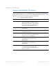
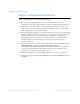

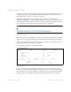
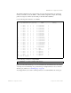
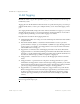
Table Of Contents
- Contents
- Figures
- Tables
- Preface
- Part 1: Basic Switching
- Accessing the Switch
- The Management Network
- Local Management Using the Console Port
- The Command Line Interface
- Remote Management Access
- Client IP Address Agents
- Securing Access to the Switch
- Setting Allowable Source IP Address Ranges
- RADIUS Authentication and Authorization
- TACACS+ Authentication
- LDAP Authentication and Authorization
- Secure Shell and Secure Copy
- Configuring SSH/SCP Features on the Switch
- Configuring the SCP Administrator Password
- Using SSH and SCP Client Commands
- SSH and SCP Encryption of Management Messages
- Generating RSA Host and Server Keys for SSH Access
- SSH/SCP Integration with Radius Authentication
- SSH/SCP Integration with TACACS+ Authentication
- End User Access Control
- Ports and Trunking
- Port-Based Network Access Control
- VLANs
- Spanning Tree Protocol
- RSTP and MSTP
- Link Layer Discovery Protocol
- Quality of Service
- Accessing the Switch
- Part 2: IP Routing
- Basic IP Routing
- Routing Information Protocol
- IGMP
- OSPF
- OSPF Overview
- OSPF Implementation in BLADE OS
- OSPF Configuration Examples
- Remote Monitoring
- Part 3: High Availability Fundamentals
- High Availability
- Layer 2 Failover
- Server Link Failure Detection
- VRRP Overview
- Failover Methods
- BLADE OS Extensions to VRRP
- Virtual Router Deployment Considerations
- High Availability Configurations
- High Availability
- Part 4: Appendices
- Index

BLADE OS 5.1 Application Guide
88 Chapter 4: VLANs BMD00113, September 2009
Ports are grouped into broadcast domains by assigning them to the same VLAN. Frames received in
one VLAN can only be forwarded within that VLAN, and multicast, broadcast, and unknown
unicast frames are flooded only to ports in the same VLAN.
The HP GbE2c Ethernet Blade Switch (GbE2c) supports jumbo frames with a Maximum
Transmission Unit (MTU) of 9,216 bytes. Within the frame, 18 bytes are reserved for the Ethernet
header and CRC trailer. The remaining 9,198 bytes comprise the packet, which includes the payload
of up to9,000 bytes, and any additional overhead such as 802.1q or VLAN tags.
Note – Jumbo frames are not supported for traffic sent to switch management interfaces.
VLANs and Port VLAN ID Numbers
VLAN Numbers
BLADE OS supports up to 1000 VLANs per switch. Even though the maximum number of VLANs
supported at any given time is 1000, each can be identified with any number between 1 and 4095.
VLAN 1 is the default VLAN for the uplink ports and the downlink ports. VLAN 4095 is reserved
switch management port 19 and cannot be configured.
Use the following command to view VLAN information:
PVID Numbers
Each port in the switch has a default VLAN number which is used for traffic that is not already
assigned to a specific VLAN. The default port VLAN identifier is known as the PVID. By default,
all non-management ports are given a PVID of 1. This places all ports on the same default VLAN
initially, although each port PVID is configurable to any VLAN number between 1 and 4094.
>> /info/l2/vlan
VLAN Name Status Ports
---- -------------------------------- ------ -----------------------
1 Default VLAN ena 1-3 5-16 20-24
2 VLAN 2 ena 4
3 VLAN 3 ena empty
4095 Mgmt VLAN ena 19
Private-VLAN Type Mapped-To Status Ports
------------ --------- ----------- ---------- -----------------
2 isolated 3 ena 4
3 primary 2 ena empty