
BLADE OS™ Application Guide HP GbE2c Ethernet Blade Switch for c-Class BladeSystem Version 5.1 Advanced Functionality Software
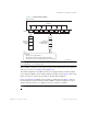
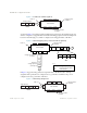
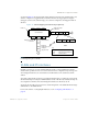
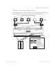
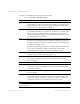
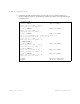
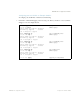
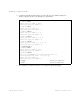
Table Of Contents
- Contents
- Figures
- Tables
- Preface
- Part 1: Basic Switching
- Accessing the Switch
- The Management Network
- Local Management Using the Console Port
- The Command Line Interface
- Remote Management Access
- Client IP Address Agents
- Securing Access to the Switch
- Setting Allowable Source IP Address Ranges
- RADIUS Authentication and Authorization
- TACACS+ Authentication
- LDAP Authentication and Authorization
- Secure Shell and Secure Copy
- Configuring SSH/SCP Features on the Switch
- Configuring the SCP Administrator Password
- Using SSH and SCP Client Commands
- SSH and SCP Encryption of Management Messages
- Generating RSA Host and Server Keys for SSH Access
- SSH/SCP Integration with Radius Authentication
- SSH/SCP Integration with TACACS+ Authentication
- End User Access Control
- Ports and Trunking
- Port-Based Network Access Control
- VLANs
- Spanning Tree Protocol
- RSTP and MSTP
- Link Layer Discovery Protocol
- Quality of Service
- Accessing the Switch
- Part 2: IP Routing
- Basic IP Routing
- Routing Information Protocol
- IGMP
- OSPF
- OSPF Overview
- OSPF Implementation in BLADE OS
- OSPF Configuration Examples
- Remote Monitoring
- Part 3: High Availability Fundamentals
- High Availability
- Layer 2 Failover
- Server Link Failure Detection
- VRRP Overview
- Failover Methods
- BLADE OS Extensions to VRRP
- Virtual Router Deployment Considerations
- High Availability Configurations
- High Availability
- Part 4: Appendices
- Index
BLADE OS 5.1 Application Guide
92 Chapter 4: VLANs BMD00113, September 2009
Figure 7 Port-Based VLAN Assignment
As shown in Figure 8, the untagged packet is marked (tagged) as it leaves the switch through port 5,
which is configured as a tagged member of VLAN 2. The untagged packet remains unchanged as it
leaves the switch through port 7, which is configured as an untagged member of VLAN 2.
Figure 8 802.1Q Tagging (after port-based VLAN assignment)
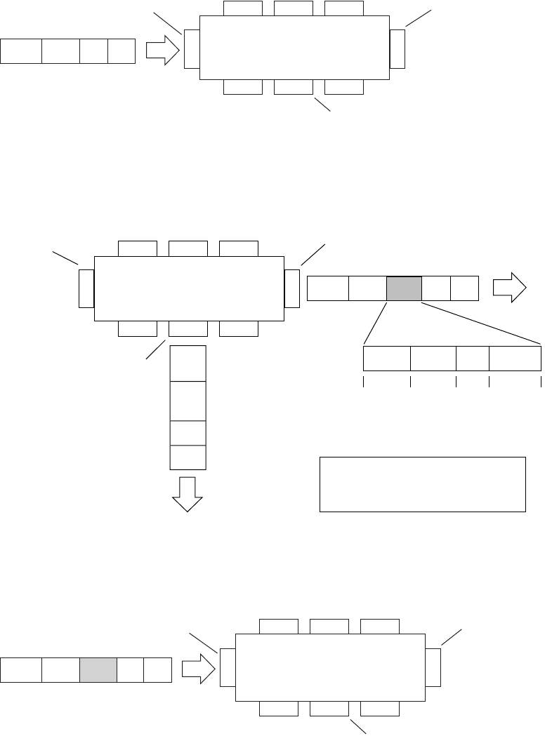
In Figure 9, tagged incoming packets are assigned directly to VLAN 2 because of the tag
assignment in the packet. Port 5 is configured as a tagged member of VLAN 2, and port 7 is
configured as an untagged member of VLAN 2.
Figure 9 802.1Q Tag Assignment
Port 6
DASADataCRC
Port 7 Port 8
Port 1
Port 4
Port 5
Port 2 Port 3
802.1Q Switch
PVID = 2
Untagged packet
Untagged member
of VLAN 2
Tagged member
of VLAN 2
B
e
f
o
r
e
Port 6 Port 7 Port 8
Port 1
Port 4
Port 5
Port 2 Port 3
802.1Q Switch
Key
Priority
CFI
VID
- User_priority
- Canonical format indicator
- VLAN identifier
PVID = 2
Tagged member
of VLAN 2
Untagged memeber
of VLAN 2
After
DA
SA
Data
CRC
(*Recalculated)
Outgoing
untagged packet
(unchanged)
DASADataCRC* Tag
VID = 2Priority
16 bits 3 bits 1 bits 12 bits
8100 CFI
Port 6
DASATagDataCRC
Tagged packet
Port 7 Port 8
Port 1
Port 4
Port 5
Port 2 Port 3
802.1Q Switch
PVID = 2
Untagged member
of VLAN 2
Tagged member
of VLAN 2
B
e
f
o
r
e