
BLADE OS™ Application Guide HP GbE2c Ethernet Blade Switch for c-Class BladeSystem Version 5.1 Advanced Functionality Software
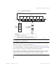
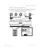
Table Of Contents
- Contents
- Figures
- Tables
- Preface
- Part 1: Basic Switching
- Accessing the Switch
- The Management Network
- Local Management Using the Console Port
- The Command Line Interface
- Remote Management Access
- Client IP Address Agents
- Securing Access to the Switch
- Setting Allowable Source IP Address Ranges
- RADIUS Authentication and Authorization
- TACACS+ Authentication
- LDAP Authentication and Authorization
- Secure Shell and Secure Copy
- Configuring SSH/SCP Features on the Switch
- Configuring the SCP Administrator Password
- Using SSH and SCP Client Commands
- SSH and SCP Encryption of Management Messages
- Generating RSA Host and Server Keys for SSH Access
- SSH/SCP Integration with Radius Authentication
- SSH/SCP Integration with TACACS+ Authentication
- End User Access Control
- Ports and Trunking
- Port-Based Network Access Control
- VLANs
- Spanning Tree Protocol
- RSTP and MSTP
- Link Layer Discovery Protocol
- Quality of Service
- Accessing the Switch
- Part 2: IP Routing
- Basic IP Routing
- Routing Information Protocol
- IGMP
- OSPF
- OSPF Overview
- OSPF Implementation in BLADE OS
- OSPF Configuration Examples
- Remote Monitoring
- Part 3: High Availability Fundamentals
- High Availability
- Layer 2 Failover
- Server Link Failure Detection
- VRRP Overview
- Failover Methods
- BLADE OS Extensions to VRRP
- Virtual Router Deployment Considerations
- High Availability Configurations
- High Availability
- Part 4: Appendices
- Index
BLADE OS 5.1 Application Guide
BMD00113, September 2009 Chapter 4: VLANs 93
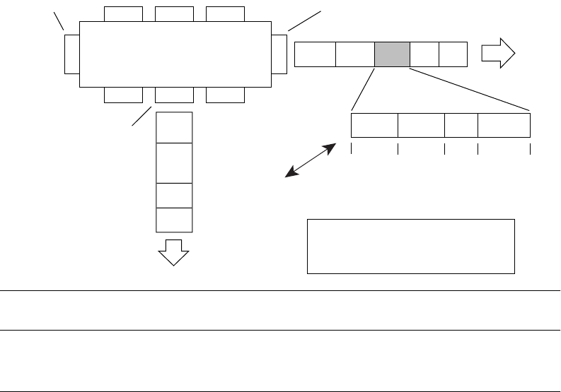
As shown in Figure 10, the tagged packet remains unchanged as it leaves the switch through port 5,
which is configured as a tagged member of VLAN 2. However, the tagged packet is stripped
(untagged) as it leaves the switch through port 7, which is configured as an untagged member of
VLAN 2.
Figure 10 802.1Q Tagging (after 802.1Q tag assignment)
Note – Set the configuration to factory default (/boot/conf factory) to reset all
non-management ports to VLAN 1.
VLANs and IP interfaces
Carefully consider how you create VLANs within the switch, so that communication with the
switch remains possible. In order to access the switch for remote configuration, trap messages, and
other management functions, be sure that at least one IP interface on the switch has a VLAN
defined.
You can also inadvertently cut off access to management functions if you exclude the ports from the
VLAN membership. For example, if all IP interfaces are left on VLAN 1 (the default), and all ports
are configured for VLAN 2, then switch management features are effectively cut off.
To remedy this, keep all ports used for remote switch management on the default VLAN and assign
an IP interface to the default VLAN.
For more information on configuring IP interfaces, see the “Configuring an IP Interface” on
page 26.
Port 6 Port 7 Port 8
Port 1
Port 4
Port 5
Port 2 Port 3
802.1Q Switch
Key
Priority
CFI
VID
- User_priority
- Canonical format indicator
- VLAN identifier
PVID = 2
Tagged member
of VLAN 2
Untagged member
of VLAN 2
After
DA
SA
Data
CRC*
(*Recalculated)
Outgoing
untagged packet
changed
(tag removed)
DASADataCRC Tag
VID = 2Priority
16 bits 3 bits 1 bit 12 bits
8100 CFI