
BLADE OS™ Application Guide HP GbE2c Ethernet Blade Switch for c-Class BladeSystem Version 5.1 Advanced Functionality Software
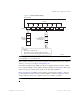
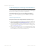
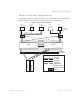
Table Of Contents
- Contents
- Figures
- Tables
- Preface
- Part 1: Basic Switching
- Accessing the Switch
- The Management Network
- Local Management Using the Console Port
- The Command Line Interface
- Remote Management Access
- Client IP Address Agents
- Securing Access to the Switch
- Setting Allowable Source IP Address Ranges
- RADIUS Authentication and Authorization
- TACACS+ Authentication
- LDAP Authentication and Authorization
- Secure Shell and Secure Copy
- Configuring SSH/SCP Features on the Switch
- Configuring the SCP Administrator Password
- Using SSH and SCP Client Commands
- SSH and SCP Encryption of Management Messages
- Generating RSA Host and Server Keys for SSH Access
- SSH/SCP Integration with Radius Authentication
- SSH/SCP Integration with TACACS+ Authentication
- End User Access Control
- Ports and Trunking
- Port-Based Network Access Control
- VLANs
- Spanning Tree Protocol
- RSTP and MSTP
- Link Layer Discovery Protocol
- Quality of Service
- Accessing the Switch
- Part 2: IP Routing
- Basic IP Routing
- Routing Information Protocol
- IGMP
- OSPF
- OSPF Overview
- OSPF Implementation in BLADE OS
- OSPF Configuration Examples
- Remote Monitoring
- Part 3: High Availability Fundamentals
- High Availability
- Layer 2 Failover
- Server Link Failure Detection
- VRRP Overview
- Failover Methods
- BLADE OS Extensions to VRRP
- Virtual Router Deployment Considerations
- High Availability Configurations
- High Availability
- Part 4: Appendices
- Index

BLADE OS 5.1 Application Guide
94 Chapter 4: VLANs BMD00113, September 2009
VLAN Topologies and Design Considerations
By default, all switch ports are configured to the default VLAN 1. This configuration groups all
ports into the same broadcast domain. The VLAN has an 802.1Q VLAN ID of 1. VLAN tagging is
turned off, because, by default, all ports are members of a single VLAN only.
If configuring Spanning Tree Protocol (/cfg/l2/stp), note that each of spanning tree
groups 2–128 may contain only one VLAN. If configuring Multiple Spanning Tree Protocol
(/cfg/l2/mrst), each of the spanning tree groups (1–32 for MSTP) may contain multiple
VLANs.
VLAN Configuration Rules
VLANs operate according to specific configuration rules. When creating VLANs, consider the
following rules that determine how the configured VLAN reacts in any network topology:
All ports involved in trunking and port mirroring must have the same VLAN configuration. If a
port is on a trunk with a mirroring port, the VLAN configuration cannot be changed. For more
information on port trunking, see “Port Trunking Example” on page 70.
All ports involved in Port Mirroring must have memberships in the same STP group, though
they can have memberships in different VLANs. For more information on configuring port mir-
roring, see “Troubleshooting” on page 253.
When you delete a VLAN, untagged ports are moved to the default VLAN (VLAN 1). Tagged
ports that belong only to the deleted VLAN are moved to the default VLAN 1. Tagged ports that
belong to multiple VLANs are removed from the deleted VLAN only.