
BLADE OS™ Application Guide HP GbE2c Ethernet Blade Switch for c-Class BladeSystem Version 5.1 Advanced Functionality Software
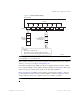
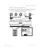
Table Of Contents
- Contents
- Figures
- Tables
- Preface
- Part 1: Basic Switching
- Accessing the Switch
- The Management Network
- Local Management Using the Console Port
- The Command Line Interface
- Remote Management Access
- Client IP Address Agents
- Securing Access to the Switch
- Setting Allowable Source IP Address Ranges
- RADIUS Authentication and Authorization
- TACACS+ Authentication
- LDAP Authentication and Authorization
- Secure Shell and Secure Copy
- Configuring SSH/SCP Features on the Switch
- Configuring the SCP Administrator Password
- Using SSH and SCP Client Commands
- SSH and SCP Encryption of Management Messages
- Generating RSA Host and Server Keys for SSH Access
- SSH/SCP Integration with Radius Authentication
- SSH/SCP Integration with TACACS+ Authentication
- End User Access Control
- Ports and Trunking
- Port-Based Network Access Control
- VLANs
- Spanning Tree Protocol
- RSTP and MSTP
- Link Layer Discovery Protocol
- Quality of Service
- Accessing the Switch
- Part 2: IP Routing
- Basic IP Routing
- Routing Information Protocol
- IGMP
- OSPF
- OSPF Overview
- OSPF Implementation in BLADE OS
- OSPF Configuration Examples
- Remote Monitoring
- Part 3: High Availability Fundamentals
- High Availability
- Layer 2 Failover
- Server Link Failure Detection
- VRRP Overview
- Failover Methods
- BLADE OS Extensions to VRRP
- Virtual Router Deployment Considerations
- High Availability Configurations
- High Availability
- Part 4: Appendices
- Index
BLADE OS 5.1 Application Guide
BMD00113, September 2009 Chapter 4: VLANs 95
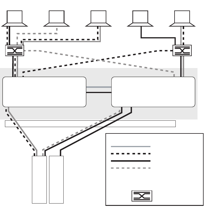
Multiple VLANs with Tagging Adapters
The following example shows only those switch port to server links that must be configured for the
example. While not shown, all other server links remain set at their default settings.
Figure 11 Multiple VLANs with VLAN Tagging
VLAN #1
VLAN #2
VLAN #3
VLAN #4
Tagged Port
Untagged Port
External Layer 2
Switch
Legend
T
U
Spanning Tree is Disabled in this example
Enclosure
Centerwall
Server 1
Server 2
TT U
. . .
Switch 2Switch 1
1
2
3
4
5
6
7
8
9
10
11
12
13
14
15
16
1
2
3
4
5
6
7
8
9
10
11
12
13
14
15
16
TTU
10/100/1000
Inter-switch
Crosslink
17 17
TT
18 18TT
24 23 22 21 20
2423222120
U
T
T
T
U
U
U
T
T
U
U
TT
PC #1
VLANs #2 & #3
PC #2
VLAN #4
PC #3
VLANs #1 & #2
PC #4
VLAN #3
10/100/1000
tagged adapter
PC #5
VLANs #1 & #2
TU
U
T