
BLADE OS™ Application Guide HP GbE2c Ethernet Blade Switch for c-Class BladeSystem Version 5.1 Advanced Functionality Software
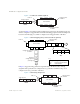
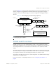
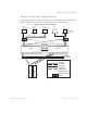
Table Of Contents
- Contents
- Figures
- Tables
- Preface
- Part 1: Basic Switching
- Accessing the Switch
- The Management Network
- Local Management Using the Console Port
- The Command Line Interface
- Remote Management Access
- Client IP Address Agents
- Securing Access to the Switch
- Setting Allowable Source IP Address Ranges
- RADIUS Authentication and Authorization
- TACACS+ Authentication
- LDAP Authentication and Authorization
- Secure Shell and Secure Copy
- Configuring SSH/SCP Features on the Switch
- Configuring the SCP Administrator Password
- Using SSH and SCP Client Commands
- SSH and SCP Encryption of Management Messages
- Generating RSA Host and Server Keys for SSH Access
- SSH/SCP Integration with Radius Authentication
- SSH/SCP Integration with TACACS+ Authentication
- End User Access Control
- Ports and Trunking
- Port-Based Network Access Control
- VLANs
- Spanning Tree Protocol
- RSTP and MSTP
- Link Layer Discovery Protocol
- Quality of Service
- Accessing the Switch
- Part 2: IP Routing
- Basic IP Routing
- Routing Information Protocol
- IGMP
- OSPF
- OSPF Overview
- OSPF Implementation in BLADE OS
- OSPF Configuration Examples
- Remote Monitoring
- Part 3: High Availability Fundamentals
- High Availability
- Layer 2 Failover
- Server Link Failure Detection
- VRRP Overview
- Failover Methods
- BLADE OS Extensions to VRRP
- Virtual Router Deployment Considerations
- High Availability Configurations
- High Availability
- Part 4: Appendices
- Index

BLADE OS 5.1 Application Guide
96 Chapter 4: VLANs BMD00113, September 2009
The features of this VLAN are described in the following table:
Note – All PCs connected to a tagged port must have an Ethernet adapter with VLAN-tagging
capability installed.
Table 10 Multiple VLANs with Tagging
Component Description
Switch 1 Switch 1 is configured for VLANS 1, 2, and 3. Port 1 is tagged to accept traffic
from VLANs 1 and 2. Ports 17 and 18 are tagged members of a trunk that accepts
traffic from VLANs 1 and 3. Port 20 is tagged to accept traffic from VLANs 1, 2,
and 3. Port 21 is an untagged member of VLAN 2.
Switch 2 Switch 2 is configured for VLANS 1, 3, and 4. Port 2 is tagged to accept traffic
from VLANS 3 and 4. Port 4 is configured only for VLAN 3, so VLAN tagging is
off. Ports 17 and 18 are tagged members of a trunk that accepts traffic from
VLANs 1 and 3. Port 20 is tagged to accept traffic from VLANs 1 and 3. Port 21
is an untagged member of VLAN 4.
Blade Server 1 This high-use blade server needs to be accessed from all VLANs and IP subnets.
The server has a VLAN-tagging adapter installed with VLAN tagging turned on.
One adapter attached to the switch is configured for VLANs 1 and 2. One adapter
is configured for VLANs 3 and 4.
Because of the VLAN tagging capabilities of both the adapter and the switch, the
server is able to communicate on all four VLANs in this network while
maintaining broadcast separation among all four VLANs and subnets.
Blade Server 2 This blade server belongs to VLAN 3. The port that the VLAN is attached to is
configured only for VLAN 3, so VLAN tagging is off.
PC #1 This PC is a member of VLAN 2 and 3. Using VLAN 2, it can communicate with
Server 1, PC 3, and PC 5. Via VLAN 3, it can communicate with Server 1,
Server 2, and PC 4.
PC #2 This PC is a member of VLAN 4, and can only communicate with Server 1.
PC #3 This PC is a member of VLAN 1 and VLAN 2. Using VLAN 1, it can
communicate with Server 1 and PC 5. Via VLAN 2, it can communicate with
Server 1, PC 1, and PC 5.
PC #4 This PC is a member of VLAN 3, and it can communicate with Server 1,
Server 2, and PC 1.
PC #5 This PC is a member of both VLAN 1 and VLAN 2. Using VLAN 1, it can
communicate with Server 1 and PC 3. Via VLAN 2, it can communicate with
Server 1, PC 1, and PC 3. The Layer 2 switch port to which it is connected is
configured for both VLAN 1 and VLAN 2 and has tagging enabled.