
AD278A/AD279A PCI MUX Support Guide, June 2006


Peripheral Connections
RS-232 Asynchronous: DB-25
Appendix B
45
RS-232 Asynchronous: DB-25
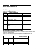
This section provides pin diagrams for DB-25 cable.
DB-25 Pin Assignments
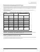
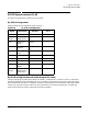
Table B-1 lists the DB-25 pin assigments.
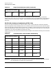
DB-25 Software Handshaking (XON/XOFF) Cable
The three-wire cable is sufficient for a terminal, printer, or other DTE (Data Terminal Equipment) devices
configured for software flow control.
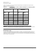
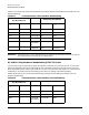
Table B-2 lists the pin-out connection between the DB25 adapter and the DB-25 terminal/printer.
Table B-1 DB-25 Pin Assignments
Signal Description DTE Use Pin #
GND Chassis Ground N/A Shell
TXD Transmitted Data Output 2
RXD Received Data Input 3
RTS Request to Send Output 4
CTS Clear to Send Input 5
DSR Data Set Ready Input 6
SG Signal Ground Reference 7
DCD Data Carrier
Detect
Input 8
DTR Data Terminal
Ready
Output 20
RI Ring Indicator Input 22
Table B-2 Simple Terminal/Printer Cable
DB-25 Female (Card End)
DB-25 Male (Peripheral)
Signal Pin Pin Signal
TxD 2 Connected to 3 RxD
RxD 3 Connected to 2 TxD
SG 7 Connected to 7 SG